A stainless steel wire mesh filter cartridge combines selected woven media, support layers, end fittings and sealing interfaces into a replaceable cylindrical assembly. Specify the complete cartridge—not only the mesh count—to control fit, flow direction and bypass risk.
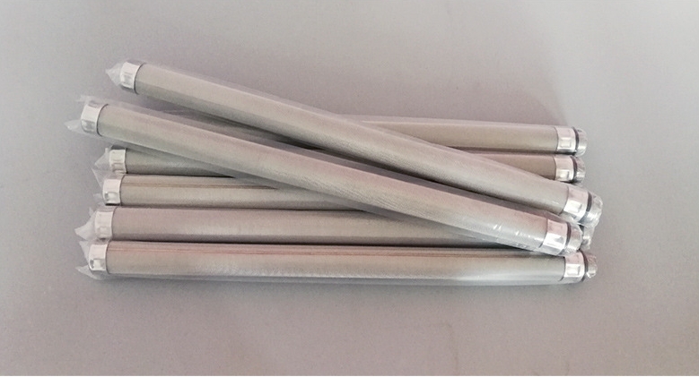
Straight wire mesh cartridge assemblies with drawing-defined lengths and end interfaces.
What Defines a Wire Mesh Filter Cartridge?
Filter media
Square woven, Dutch weave or multilayer media selected from the retention requirement.
Support structure
Perforated, expanded or coarse mesh backing arranged for the actual pressure direction.
End interfaces
Caps, collars, threads, flanges and sealing faces matched to the receiving equipment.
Finished assembly
OD, ID, length, concentricity, seam, active area and cleanability controlled together.
Wire Mesh Filter Cartridge Specification Table
RFQ field
Information to provide
Why it matters
Finished dimensions
OD, ID, overall length, active length, wall stack and tolerances
Controls installation fit and usable filtration area
Filter media
Material, weave, mesh/wire or aperture; rating basis where applicable
Defines retention geometry and media compatibility
Support layers
Type, thickness, opening, position, orientation and joining
Supports the media in the specified pressure direction
End fitting
Thread standard, flange, collar, cap, opening and datum
Matches the equipment connection and replacement method
Sealing interface
Gasket type, groove, sealing face, compression direction and finish
Limits bypass around the cartridge
Operating duty
Fluid, flow, temperature, differential pressure, contaminants and cleaning
Guides media, support and joint selection
Fine media, external support and threaded connections must be specified as one assembly.
Media and Support Layer Construction
Fine woven media controls the filtration opening or retention path. A support core or outer cage may stabilize that media, but support location must match the inside-to-outside or outside-to-inside flow direction.
State every layer in order. Do not assume that a visible outer cage proves the same pressure direction for every cartridge.
Select the inner core and outer cage from the actual load path, unsupported span, media fineness, flow direction, clean and maximum differential pressure, reverse cleaning and fabrication geometry. A support type does not create a universal pressure rating.
Support form
What to specify
Buyer check
Perforated inner core
Material, thickness, hole size/pattern, open area, seam and end attachment
Does the core support the media on the high-pressure side without masking excessive area?
Expanded-metal support
SWD/LWD orientation, strand width/thickness, flattening, overlap and edge condition
Can strand edges, orientation or local overlap damage or obstruct the fine medium?
Coarse woven support
Mesh count, wire diameter, weave, layer position and joining zones
Is the support stable enough for the stated span and differential pressure?
Outer protective cage
Opening, diameter, clearance, rings, joints and media contact points
Is it carrying reverse pressure, protecting handling, or performing both functions?
Drainage / distribution layer
Layer geometry, flow order, contact and allowed masked area
Do not describe drainage and structural support as automatically equivalent.
Inside-to-outside flow
The inner core may carry the fine media when pressure acts outward, subject to the complete layer arrangement.
Outside-to-inside flow
An inner support can receive inward loading, while an outer cage may serve protection or reverse-duty needs.
Bidirectional or backwash duty
State normal and reverse differential pressure separately and review support on both sides where required.
Use the filter flow-direction and support guide for layer-order drawing notation. Support-core opening and filtration-media rating must remain separate RFQ fields.
Available Cartridge Configurations
Straight woven-mesh cartridge
Smooth cylindrical media with drawing-defined seams, ends and optional support.
Internally supported cartridge
Fine outer media backed by a perforated or expanded inner core.
Externally supported cartridge
Fine inner media protected or restrained by an outer support layer.
Threaded-end cartridge
Replaceable assembly with a specified thread and sealing shoulder.
Flanged or collared cartridge
Equipment interface controlled by flange geometry, holes, faces and gaskets.
Closed-end cartridge
One end capped or formed with the opposite end used for connection or flow.
Straight wire mesh cartridge assemblies with drawing-defined lengths and end interfaces.
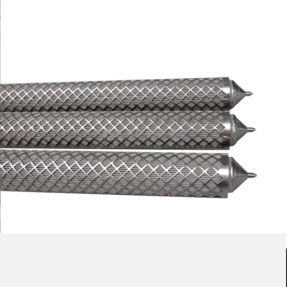
Expanded outer support protects fine filter media in a drawing-specific cartridge construction.
End Fittings, Seals and Replacement Fit
A cartridge differs from a plain cylinder because the equipment interface is part of the product. Show thread designation, flange or collar dimensions, sealing face, groove, gasket position, insertion depth and removal clearance on the drawing.
Stainless Steel Candle Filter Element: A Cartridge Form, Not a Separate Rating
Candle geometry
Usually a long, narrow cylindrical element whose installed length and straightness must match the housing.
Mounting end
Thread, flange, collar, open end or another drawing-defined connection locates and seals the element.
Closed or supported end
The opposite end may be capped, guided or supported according to the housing and flow path.
Media construction
Woven, pleated or sintered media still requires its own retention definition, support and cleaning limits.
“Candle” does not define micron rating, pressure capacity, flow direction or service life. For a replacement candle element, provide the housing drawing, installed orientation, number and spacing of elements, overall and active length, OD/ID, end connection, seal, media, support, flow, differential pressure and cleaning method.
Where the element uses woven wire mesh, this cartridge page remains the primary procurement page. Use the published end connections and sealing guide to describe a threaded, flanged, collared or plain-end interface without creating a second competing product page.
Selection Steps for Industrial Buyers
1. Define retention
State particle target, aperture or the rating method used for the media.
2. Define the duty
Provide fluid, flow, temperature, pressure direction and allowable differential pressure.
3. Define the structure
List media and every support layer from inside to outside.
4. Define the interface
Add ends, thread or flange, seals, datums and critical tolerances.
5. Define service
State cleaning method, replacement access, quantity and drawing revision.
Real Wire Mesh Filter Cartridge Examples
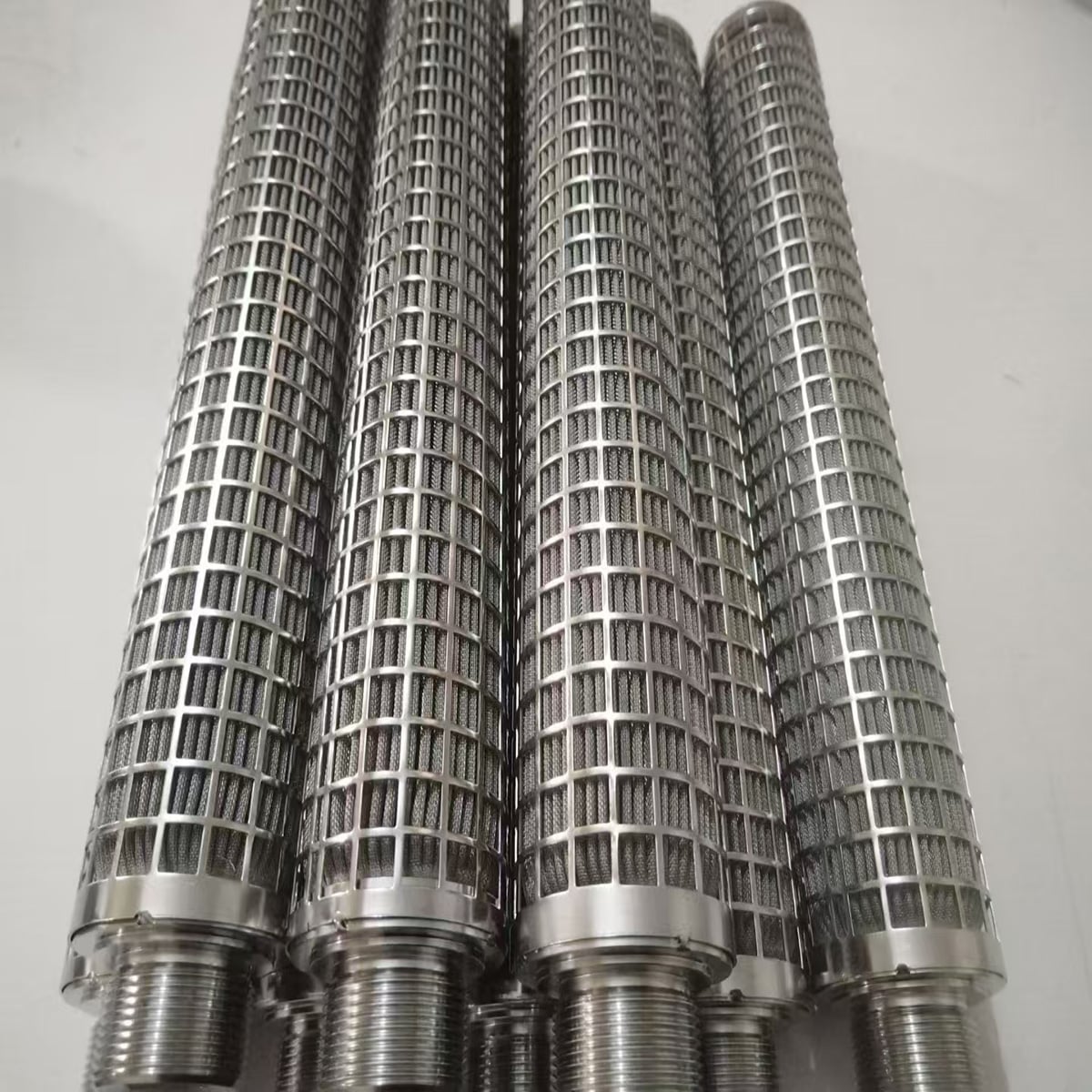
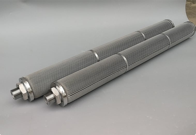
These Maidong material-library photographs show several cartridge constructions, support arrangements and end interfaces. They are examples of fabricated forms; final dimensions, media, joints and connections follow the approved drawing.
Straight wire mesh cartridge assemblies with drawing-defined lengths and end interfaces.
Straight mesh cartridges
Fine media, external support and threaded connections must be specified as one assembly.
Supported threaded cartridges
Long cartridge bodies showing threaded interfaces and intermediate support rings.
Long cartridges with support rings
Applications and Procurement Boundaries
Liquid filtration
Drawing-specific cartridges for oil, water or process-liquid duties after compatibility review.
Gas filtration
Metal media assemblies where the process conditions and required retention are defined.
Equipment protection
Replaceable inlet, circulation or return-line screening components matched to the housing.
Reusable filtration
Cleanable metal assemblies when the cleaning method and reverse-load limits are known.
No operating life, pressure drop, maximum temperature or chemical compatibility is implied without the actual process data. Use the custom filter element specification guide to prepare a complete enquiry.
Candle filter element often describes a long, narrow cylindrical cartridge installed vertically or in a multi-element housing. The terms can overlap. Specify the actual media, support, end connection, sealing interface, installed orientation and drawing rather than relying on the name alone.
A cartridge is normally a replaceable assembly with defined end fittings, sealing surfaces and installation orientation. A mesh cylinder may be only the formed screening body without a complete mounting or sealing interface.
The media may use square woven mesh, Dutch weave or a drawing-defined multilayer construction. Selection depends on the required aperture or retention basis, fluid, flow, differential pressure, cleaning method and support direction.
Yes. Fine mesh may be combined with perforated metal, expanded metal or coarse support mesh when the duty requires structural backing. The drawing should state the support position, flow direction and joining method.
Drawing-defined threaded ends, plain open ends, flanges, collars, caps and other equipment interfaces can be reviewed. Provide the thread standard, sealing face, gasket location, datum and critical tolerances.
For square woven mesh, state mesh count and wire diameter or measured aperture. For Dutch weave or a rated medium, state the complete construction and the basis of the claimed retention value; a simple mesh-to-micron conversion is not sufficient.
Send OD, ID, overall and active length, media construction, material, support layers, end fittings, seal details, flow direction, operating medium, temperature, differential pressure, cleaning method, quantity and drawing revision.
Send the Cartridge Drawing and Operating Data
Include the media, layer order, OD/ID, overall and active length, support, end fittings, seals, flow direction, operating duty, cleaning method, quantity and drawing revision.