Inside-to-Outside vs Outside-to-Inside Filter Tube Flow
Outside-to-inside flow normally pushes cylindrical filter media inward, so support is commonly placed inside. Inside-to-outside flow normally pushes media outward, so support is commonly placed outside. The final layer arrangement must follow the actual differential-pressure direction, including backwash and transient conditions.
Direct Answer: Put Support on the Loaded Side
Outside → Inside
Higher pressure outside loads the medium inward toward an internal core.
Inside → Outside
Higher pressure inside loads the medium outward toward an external cage.
Reverse or cyclic flow
Bidirectional loading may require support or restraint on both sides.
Flow Direction and Support Position Comparison
Flow arrows describe movement, while differential pressure describes mechanical loading. Specify both because a stopped, blocked or reversing system can create a different load from normal flow.
| Design condition | Outside-to-inside | Inside-to-outside | Buyer action |
|---|---|---|---|
| Upstream side | Outside cylindrical surface | Central passage | Mark inlet and upstream side |
| Net media load | Radially inward | Radially outward | State maximum differential pressure |
| Common support location | Inside the fine medium | Outside the fine medium | Show complete layer order |
| Dirty-side access | Outside surface | Inside passage | Consider cleaning access |
| Reverse-flow risk | Outward during reversal | Inward during reversal | Add reverse-load condition |
Outside-to-Inside Flow
Fluid reaches the outer surface and travels toward the central outlet. When pressure is higher outside, the fine medium is pushed inward, so a perforated, grid or expanded internal core commonly supports it.
Use the perforated filter tube page when a formed internal support core is required.
Inside-to-Outside Flow
Fluid enters the central passage and moves outward. When pressure is higher inside, the fine medium is pushed toward the outer diameter, so an external cage or shell commonly restrains it.
For finished composite builds, review multi-layer filter tubes.
Layer Order: Name Every Function
Fine retention medium
Specify weave, aperture or rating basis separately.
Drainage layer
Maintains flow paths beside the fine medium.
Structural support
Carries the stated differential-pressure load.
Protective layer
Guards finer media during handling or service.
For media terminology, see stainless steel mesh for filtration. For a complete cylindrical product family, review stainless steel filter tubes.
How to Select a Filter Mesh Support Layer
Select the support from differential-pressure direction, unsupported span, fine-media sensitivity, required open flow path, forming geometry and cleaning duty. The support should restrain the fine layer without creating an unintended bypass path or confusing the filtration rating.
| Support option | Useful when | Drawing fields | Selection caution |
|---|---|---|---|
| Coarse woven mesh | A relatively smooth, flexible backing is needed beside fine cloth | Weave, mesh count, wire diameter, orientation and layer order | It is not the retention rating unless explicitly designated |
| Welded support grid | Open-area support and repeatable wire locations suit the geometry | Opening, both wire diameters, grid direction and support span | Wire crossings and edge projections affect contact and fit |
| Expanded metal | A formed cage or protective shell needs an open rigid pattern | SWD, LWD, strand, thickness, orientation and formed diameter | Raised strands can mark or concentrate load on fine media |
| Perforated metal | A rigid core or shell needs controlled holes and a defined wall | Hole size/pattern, pitch, thickness, open area, seam and diameter | Support-hole size must not be reported as the filtration rating |
Drainage Layer vs Structural Support
A drainage layer keeps a flow path open beside fine media; a structural support carries mechanical load. One layer may contribute to both functions, but the drawing should name the intended function, construction and position instead of using the generic word “backing.”
Show whether layers are loose, spot attached, edge joined or fully bonded, and state which layer controls the finished diameter.
Write the Layer Stack in One Direction
Inside → Outside
List every layer from the center passage toward the outside surface.
Function per layer
Label retention, drainage, structural support or protection separately.
Pressure arrow
Mark normal and reverse higher-pressure sides next to the layer stack.
Example notation: inside → perforated support core → coarse drainage mesh → fine retention mesh → outside. This is a notation example only; the correct order depends on the actual flow and pressure cycle. For full dimensional controls, use the filter element drawing and tolerance checklist.
Real Support-Layer Configurations
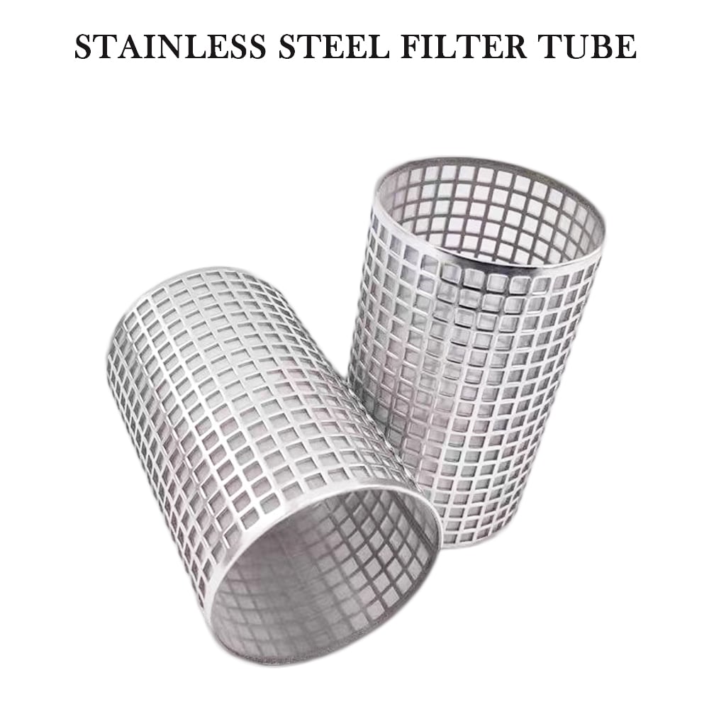
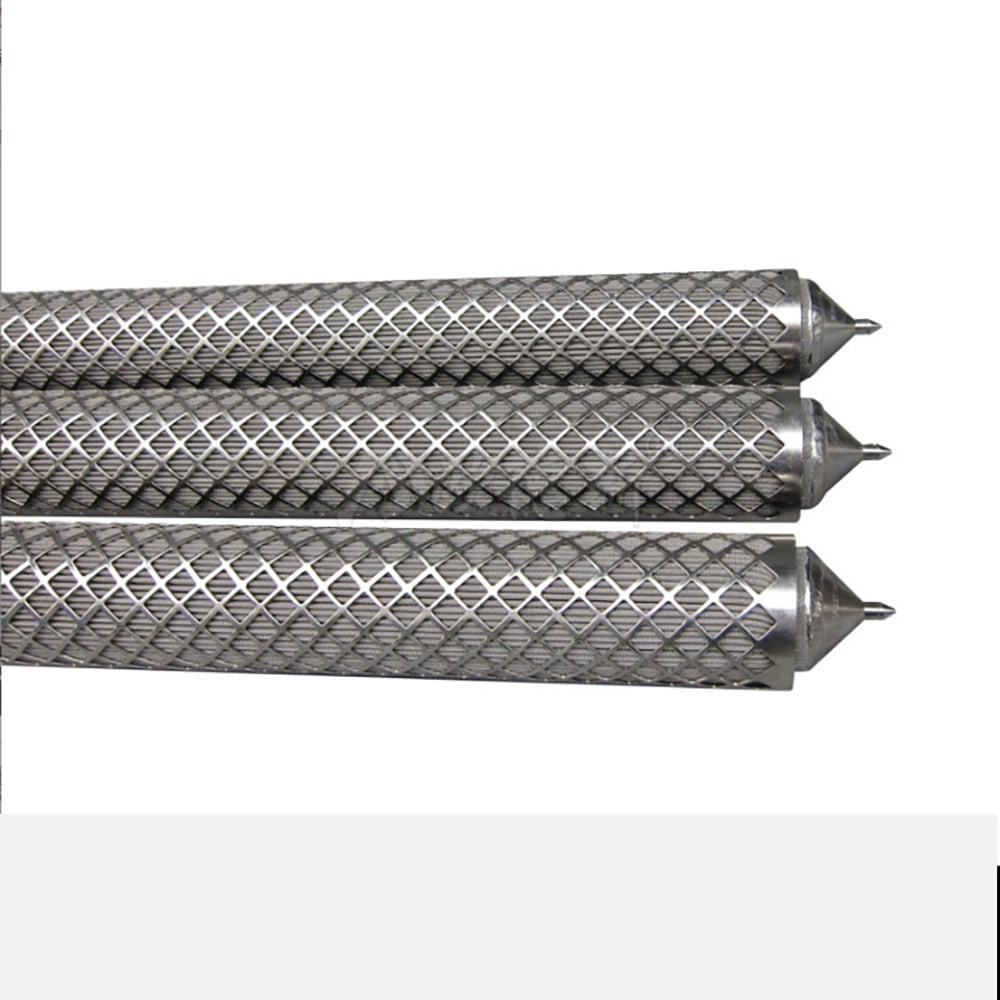
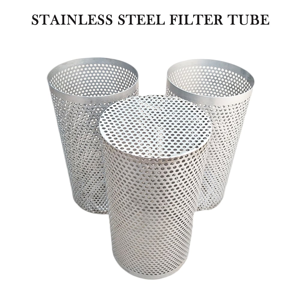
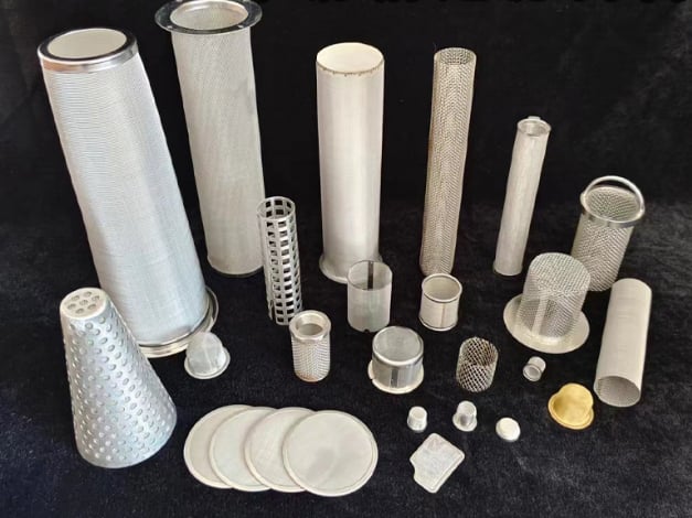
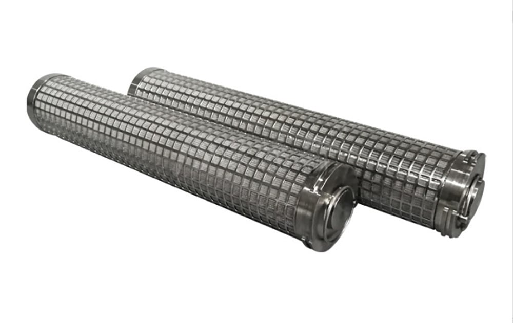
These Maidong product images show fine media with external cages, perforated bodies and open support structures. They illustrate construction options, not a universal flow direction for every product.
External square support cage
Perforated support body
Mixed cylindrical structures
Conditions That Can Reverse the Load
Backwashing
Cleaning flow can reverse the direction of media loading.
Blocked downstream path
Pressure distribution can differ from normal operation.
Start and stop transients
Short load peaks may govern support requirements.
Two-way process flow
Both directions may need defined restraint and attachment.
Filter Tube Drawing and RFQ Checklist
1. Mark flow
Add inlet, outlet and arrows for every operating mode.
2. State pressure
Give normal, maximum and reverse differential pressure.
3. List layers
Show inside-to-outside order and each layer function.
4. Dimension support
Provide opening, thickness, diameter and interfaces.
5. Complete duty
Add medium, temperature, cleaning, quantity and drawing.
Filter Tube Flow Direction FAQ
Place structural support on the side toward which the fine medium is pushed by the net differential-pressure load. For normal inward flow, support is commonly inside the fine medium; for outward flow, support is commonly outside. Confirm the complete pressure cycle rather than relying on flow wording alone.
Fluid approaches the outside cylindrical surface, passes radially inward through the media and exits through the center. If upstream pressure is higher outside, the media is loaded inward toward an internal support core.
Fluid enters the central passage, moves radially outward through the media and exits from the outer surface. If upstream pressure is higher inside, the media is loaded outward toward an external support cage or shell.
Yes. Reverse flow or cleaning can load the media in the opposite direction. State normal, maximum, transient and reverse differential pressure so the assembly can be reviewed for both directions.
No. A coarse perforated or expanded support generally carries load. The designated fine mesh or porous medium defines retention and should be specified separately.
Use arrows and labels for inlet, outlet, upstream and downstream; show inside/outside layer order; state normal and reverse differential pressure; and identify which diameter and support surface are critical.
Need a Filter Tube Structure Review?
Send the media, inside-to-outside layer order, flow arrows, normal and reverse differential pressure, dimensions, ends and operating conditions.