CUSTOM METAL FILTER · RFQ RESOURCE

Filter Element Drawing and Tolerance Checklist

A usable filter-element drawing connects filtration performance to the manufactured part. Define the media, layer order, flow direction, controlled dimensions, end interfaces, seals, joints, tolerances and inspection requirements—then distinguish critical dimensions from reference information.

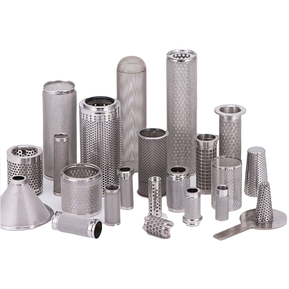
Custom metal filter elements with several geometries and end configurations
Different geometries and end interfaces require separate controlled dimensions on the drawing.

Direct Answer: A Filter Drawing Must Control Fit, Filtration and Bypass Paths

Filtration medium

Identify the material, weave or porous structure, aperture or rating basis and layer order.

Equipment fit

Control installed length, fitting diameter, seating face, thread, flange and assembly clearance.

Structural load

Show support position, flow direction and normal, maximum and reverse differential pressure.

Acceptance

State which dimensions, media properties, joints and integrity checks must be verified.

Filter Element Drawing Control Matrix

Place the functional requirement next to the dimension or construction it controls. Avoid relying on an email description that can become separated from the released drawing revision.

Drawing zoneDefineCommon risk if omitted
MediaMaterial, weave, mesh/wire or rating basis, layers and orientationWrong retention medium or ambiguous filtration claim
EnvelopeOverall length, maximum diameter, installed length and clearancePart does not fit or cannot be removed
InterfaceThread/flange, seating face, groove, gasket and datum referenceLeakage, bypass or misalignment
StructureSupport body, layer order, seam, cap, rim and attachmentMedia deformation or uncontrolled joint
TolerancesCritical fit dimensions, form, position and general tolerancesOver-control, under-control or inconsistent inspection
AcceptanceMaterial, dimension, media, joint and integrity evidenceBuyer and supplier use different acceptance rules
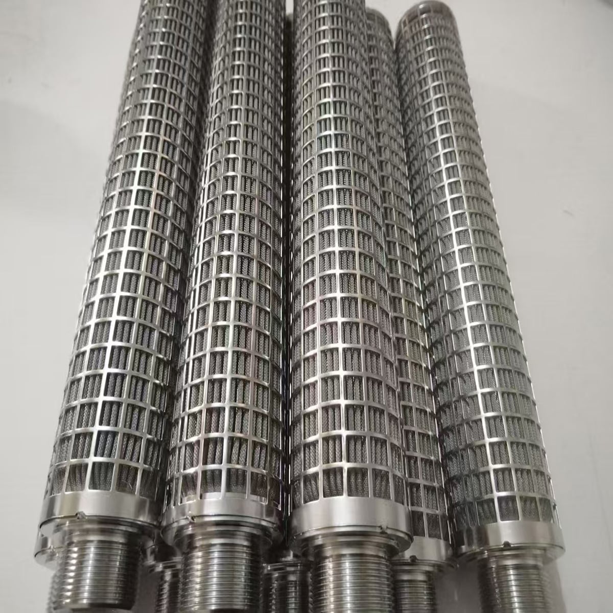
Threaded cylindrical filter elements showing male end connections
Thread form, size, engagement length, reference face and orientation should be defined together.

End Connections and Sealing Interfaces

For threads, define the standard or form, size, pitch, class or fit when applicable, engagement length and reference face. For flanges, define outside diameter, thickness, bolt pattern, hole size and sealing face. For grooves and gaskets, control the dimensions that determine compression and bypass resistance.

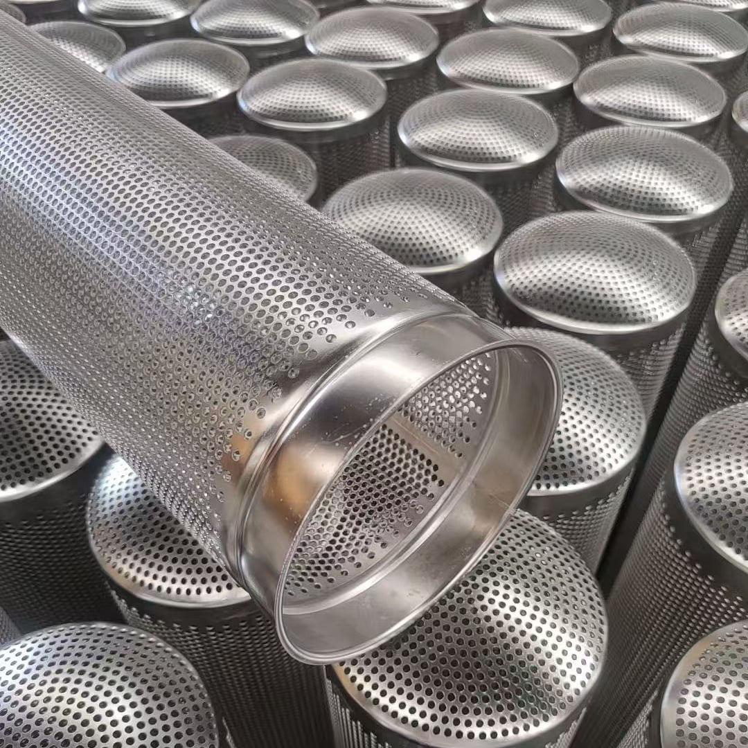
See the finished stainless steel filter tube and wire mesh cylinder structures for cylindrical component context.

Dimension and Tolerance Priorities

Critical fit dimensions

Equipment interfaces, sealing faces and installed envelope usually need explicit control.

Media dimensions

Control the filtration area, media location and any edge that can create bypass.

Form and alignment

Add straightness, roundness, flatness or position only where function requires it.

Reference dimensions

Mark calculated or informational values so they are not mistaken for inspection requirements.

Do not assign one tight general tolerance to every feature. Connect each tolerance to assembly, sealing, interchangeability, flow or inspection need.

Specify the Filter Media Separately from the Support

The fine medium defines retention; perforated sheet, expanded metal or coarse mesh usually provides support. Show the inside-to-outside layer order, attachment method and flow arrows. If reverse flow or backwashing is possible, include the reverse differential pressure.

Use the nominal vs absolute rating guide to define rating language and the filtration mesh page to compare media structures.

Metal filter elements with open and closed end cap configurations
Open, closed and stepped end configurations change overall length, sealing and installation dimensions.

Drawing Details by Element Form

Filter disc

Diameter, thickness, mesh layers, edge or frame, seating face and flatness if functional.

Filter cylinder

Inside/outside diameter, length, seam, support, ends, concentricity and flow direction.

Filter cartridge

Installed length, media area, center core, end connections, seals and allowable pressure load.

Filter basket

Body dimensions, flange, handle, bottom, seam, housing clearance and removal direction.

Real Maidong Components: Features the Drawing Must Control

These real Maidong components illustrate geometry and interface differences. They are examples of features to define, not dimensional standards or promised tolerances.

Custom metal filter elements with several geometries and end configurations
Different geometries and end interfaces require separate controlled dimensions on the drawing.

Multiple element geometries

Threaded cylindrical filter elements showing male end connections
Thread form, size, engagement length, reference face and orientation should be defined together.

Threaded interfaces

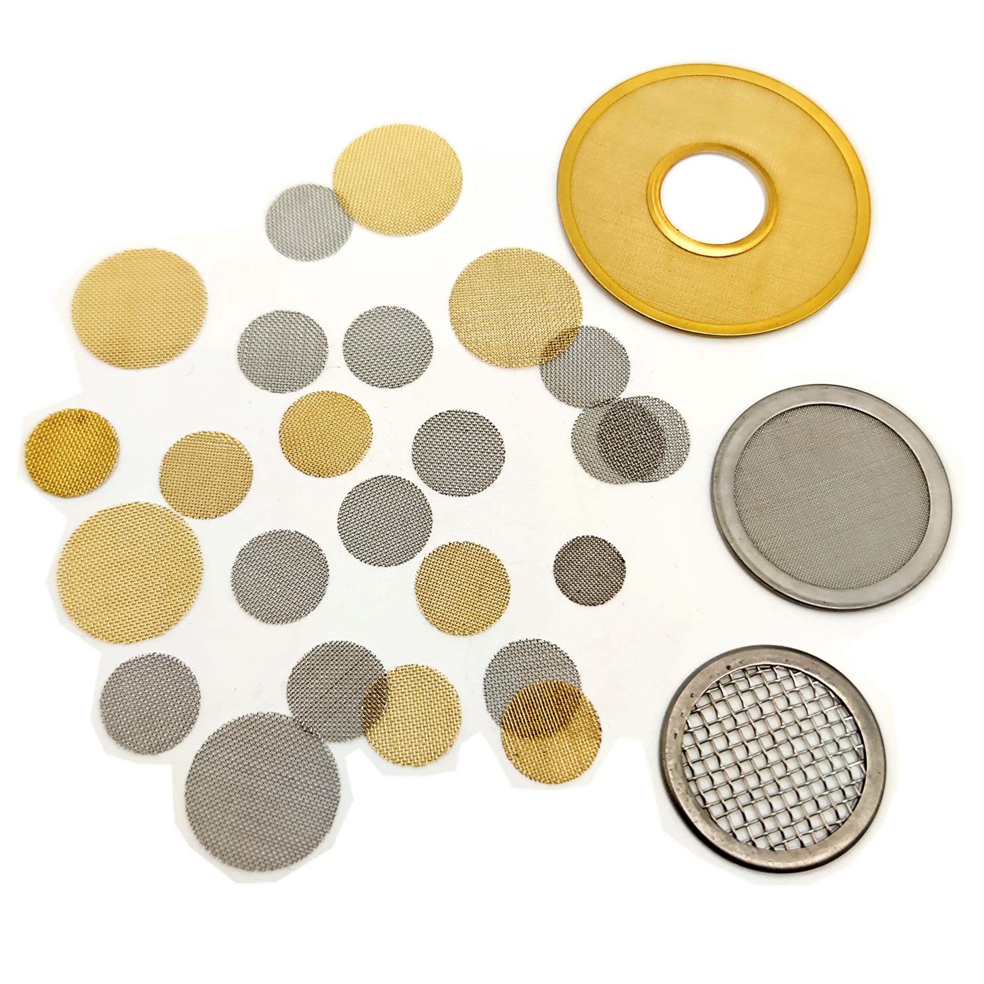
Round stainless steel wire mesh filter discs with plain and framed edges
Filter discs need controlled diameter, thickness, edge construction and seating dimensions.

Disc edges and diameters

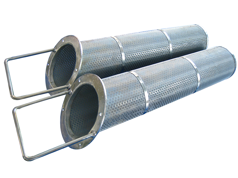
Stainless steel filter baskets with flanges handles and cylindrical bodies
Basket drawings should locate the flange, handle, body, bottom and housing-clearance dimensions.

Basket flange and handle

Filter Element Drawing Release Checklist

1. Define function

Process medium, contaminant, retention target, flow and pressure.

2. Define construction

Media, layers, support, joints, ends, seals and material.

3. Control the fit

Envelope, installation interface, datums, clearances and critical dimensions.

4. Apply tolerances

Use functional limits and identify reference versus inspected dimensions.

5. State acceptance

Documents, inspection method, integrity check, quantity and revision.

Filter Element Drawing FAQ

Critical dimensions usually include the equipment-fitting diameter, overall and installed length, sealing face, thread or flange interface, end geometry, media location and any clearance that controls assembly. Mark which dimensions are inspection-critical.
No. Apply tighter tolerances only where fit, sealing, alignment, flow or interchangeability requires them. Unnecessarily tight tolerances can restrict feasible fabrication without improving function.

State material, weave, mesh count and wire diameter or clear aperture for square mesh. For Dutch weave, sintered or other porous media, identify the complete construction and agreed rating or test basis.

Use arrows for normal and reverse flow, identify upstream and downstream sides, and list the layer order from inside to outside. State normal, maximum and reverse differential pressure.

Identify joint locations and the required attachment or sealing function. If a weld type, continuity, finish, leakage check or acceptance condition is required, state it explicitly rather than relying on a general note.

List only documents relevant to the purchase, such as material records, dimensional inspection, media or opening verification, joint inspection, integrity results or agreed certificates. Do not assume they are included unless stated in the RFQ.

Ready to Review a Custom Filter Drawing?

Send the latest drawing revision with process duty, filtration basis, materials, interfaces, critical dimensions, tolerances, inspection requirements and quantity.