A custom perforated filter tube is defined by its sheet material, thickness, hole size, pitch, pattern, diameter, seam and end details. It may function as a coarse screen, protective sleeve or support core for finer filtration media. Send a drawing so open area, strength and equipment interfaces can be reviewed together.
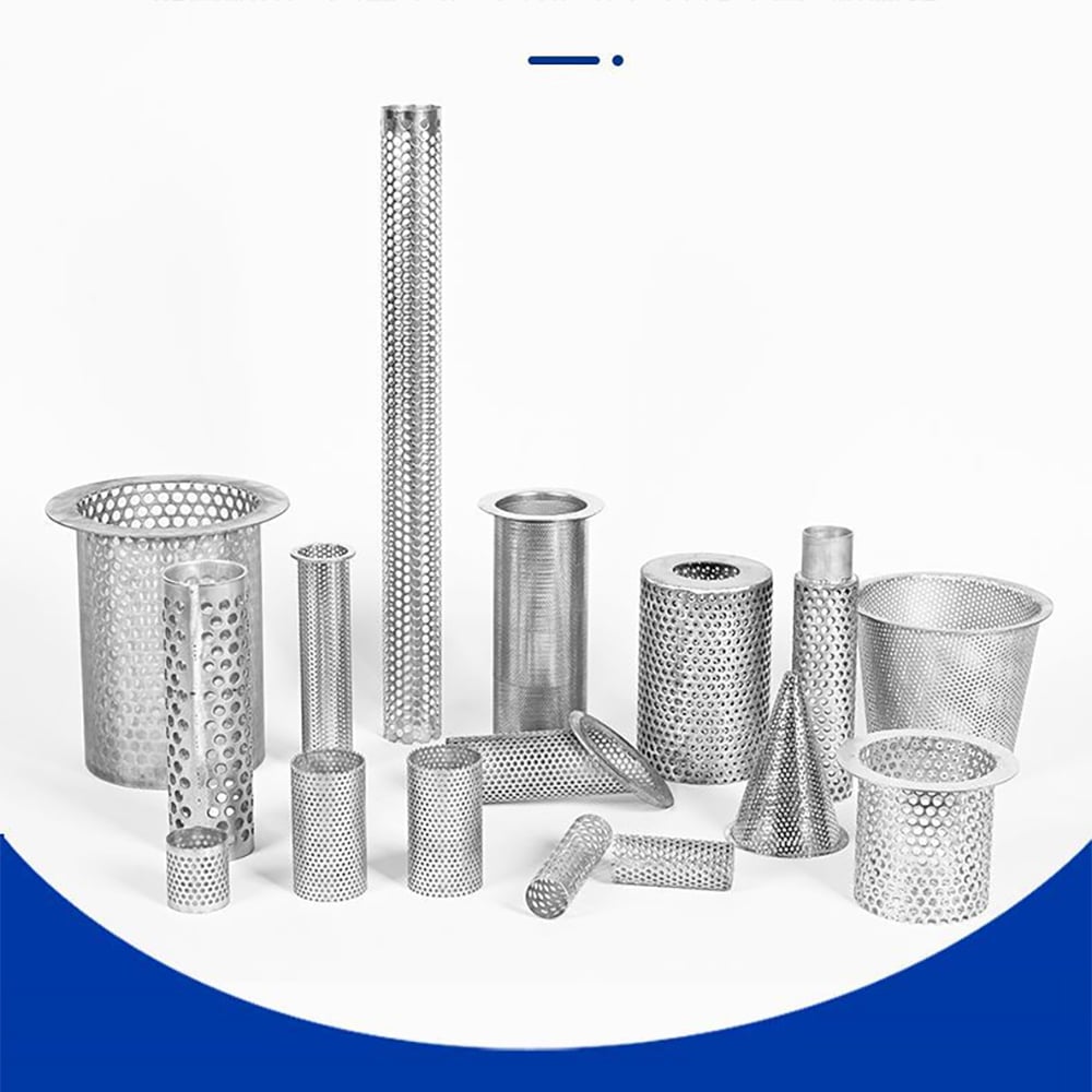
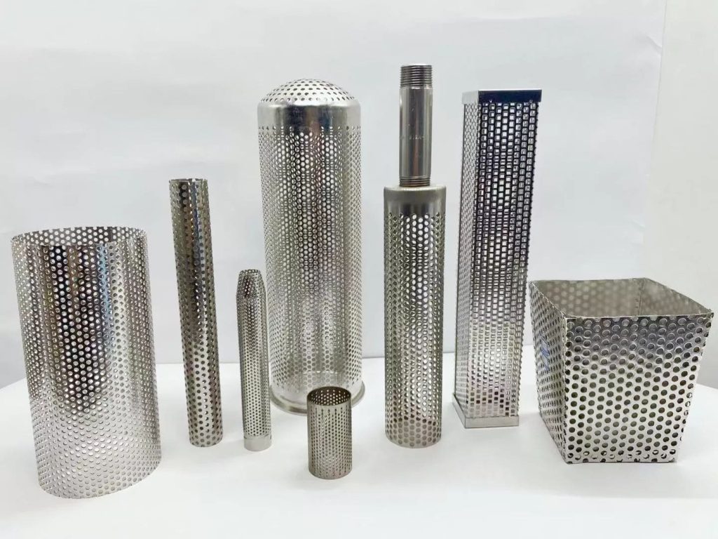
Perforated cylindrical components with different diameters, lengths and end configurations.
Perforated Tube Functions at a Glance
Coarse screening
Controlled holes retain larger particles while allowing liquid, gas or bulk material to pass.
Filter support core
A rigid body supports woven mesh or other fine media against differential pressure.
Protective sleeve
Outer perforated structure helps protect finer media from handling or mechanical impact.
Fabricated component
Tube body combined with flanges, caps, collars, handles or mounting features from a drawing.
Perforated Filter Tube Specification Checklist
Hole diameter alone is not a complete specification. Pitch, pattern, sheet thickness, unperforated margins and formed-tube dimensions should be shown together.
Mobile: swipe sideways to view every column.
RFQ field
What to specify
Design relevance
Material
Alloy/grade and any required finish
Relates to corrosion, forming, welding and service environment
Sheet thickness
Nominal thickness and applicable tolerance
Affects rigidity, forming radius and hole feasibility
Hole geometry
Shape, size, pitch, pattern and orientation
Defines open area, ligament and screening behavior
Tube geometry
OD or ID, length, roundness and critical tolerances
Controls equipment fit and assembly clearance
Seam
Longitudinal joint and weld requirements
Influences structural continuity and finished geometry
Ends/interfaces
Open/closed ends, caps, flange, collar, thread or handle
Defines mounting, sealing and removal requirements
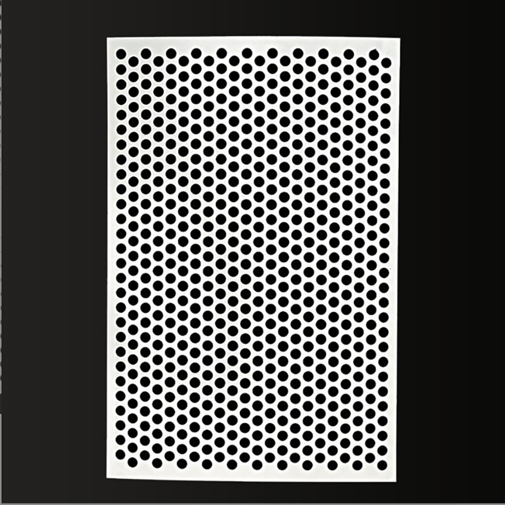
Round-hole pattern showing hole diameter, pitch and ligament relationship.
Hole Size, Pitch and Open Area
Hole size controls the nominal clear opening. Pitch is the center-to-center distance between adjacent holes. Ligament is the metal remaining between openings. Their relationship affects theoretical open area and sheet strength.
Theoretical sheet open area is not automatically the same as the effective open area of a finished tube because seams, end margins, flanges and support layers may block part of the flow area.
A common choice for predictable spacing and general screening or support duties.
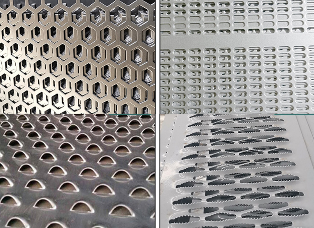
Slots and custom shapes
Orientation and ligament must be defined because elongated openings behave differently by direction.
Metal selection
Stainless steel, carbon steel or coated material can be reviewed against corrosion, forming and welding needs.
Tube, Cylinder and Fabricated Shapes
Tube and cylinder usually describe the same product family. The important distinction is the drawing: circular or non-round body, diameter, length, seam, ends and mounting features.
Different duty: this page covers screening and filter-media support. A perforated gas sparger tube uses drawing-defined outlets to distribute gas into a process zone or liquid; its inlet conditions, hole map and distribution validation belong to a separate specification.
Perforated Tube Selection Workflow
1. Define the function
Coarse screen, support core, protective sleeve or complete strainer.
2. Specify perforation
State hole shape, size, pitch, pattern, orientation and margins.
3. Define the body
Provide material, thickness, OD/ID, length, seam and tolerances.
4. Add filter layers
Show fine mesh, support position and flow direction if a composite is needed.
5. Complete the drawing
Include ends, connections, operating conditions, quantity and required documents.
Representative perforation shapes; final availability is reviewed from the drawing.
What to Include in Your RFQ
Material grade and sheet thickness
Hole shape, size, pitch and arrangement
OD/ID, length and tolerances
Unperforated margins and seam details
Ends, flanges, caps, collars or fittings
Fine mesh/support layers and flow direction
Operating conditions, drawing and quantity
Photos can clarify the concept, but dimensions and critical requirements should be provided in a drawing.
A perforated filter tube is formed from metal sheet with a controlled hole pattern and joined into a cylindrical or drawing-specific body. It can act as a coarse screen, protective sleeve or structural support beneath finer filter media.
State the material, sheet thickness, hole shape and size, pitch or center spacing, pattern orientation, outside or inside diameter, length, seam, edge condition, end details, tolerances, quantity and intended service.
For a 60-degree staggered round-hole pattern, theoretical open area depends on hole diameter divided by pitch. The calculation must use the actual pattern and center spacing; formed-tube geometry, margins and unperforated areas can change the effective component open area.
Usually it provides coarse screening or structural support. Fine filtration commonly requires woven wire mesh, Dutch weave or another porous medium added to the perforated body. The complete layer structure should be specified.
The terms frequently describe the same cylindrical component. Tube often emphasizes a long body or pipe-like geometry, while cylinder is broader. Selection should be based on the drawing, not the wording alone.
Drawing-based parts can be reviewed with flanges, collars, open or closed ends, caps, fittings, handles and mounting details. Critical interfaces and weld requirements should be shown on the drawing.
Request a Perforated Tube Drawing Review
Send the material, thickness, hole pattern, diameter, length, seam, ends and operating conditions. Maidong can review a perforated filter tube or support cylinder enquiry.