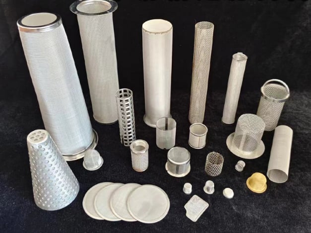
A perforated filter element support core is the load-carrying cylinder behind fine filter media. Specify it by finished diameter, length, thickness, hole geometry, pitch, pattern, seam, solid margins, ends and differential-pressure direction—not by nominal pipe size alone.
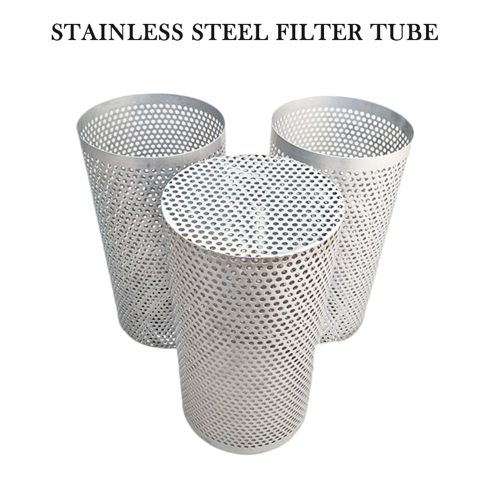
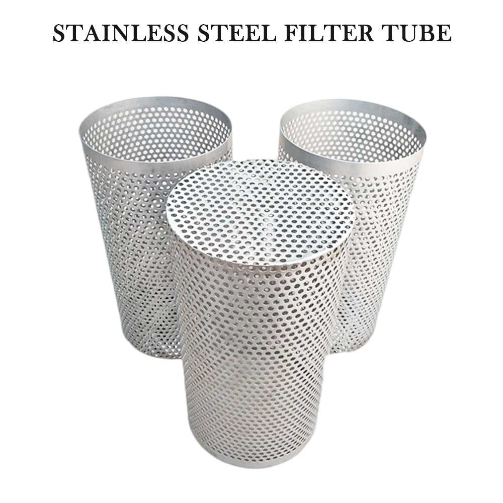
Perforated cylindrical bodies used as structural cores in custom filter assemblies.
Direct Answer: Support Structure and Filtration Media Are Different
Support load
The core limits deformation of fine media under the stated differential-pressure direction.
Maintain geometry
Finished diameter, roundness and straightness help control the assembled cartridge envelope.
Preserve flow path
Hole pattern and effective open area provide drainage behind the retention layer.
Protect the interface
Seams, ends and solid margins must not create abrasion or bypass paths.
Perforated Support Core Specification Table
A complete drawing separates support perforation from the fine-media opening or filtration rating.
RFQ field
What to specify
Why it matters
Material
Alloy/grade and required documentation
Compatibility and assembly material control
Finished geometry
OD, ID if controlled, length, thickness, roundness and straightness
Fit, media support and assembly clearance
Perforation
Hole shape and size, pitch, pattern, orientation and margins
Support span, drainage and effective open area
Seam and ends
Joint type, overlap, weld scope, open/closed ends and adapters
Strength, media contact and interface integrity
Operating load
Flow direction plus normal, maximum and reverse differential pressure
Determines which side requires structural restraint
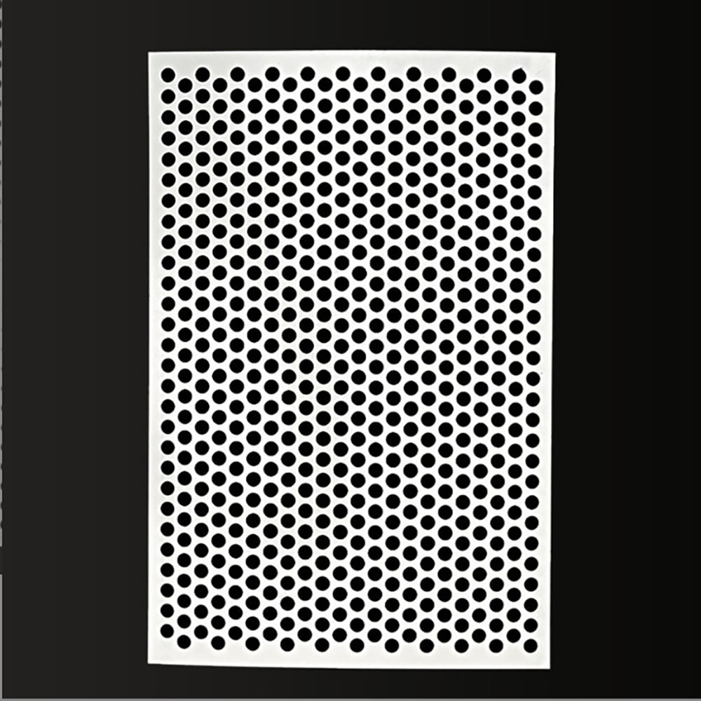
Round-hole pattern illustrating hole diameter, pitch and ligament.
Hole Size, Pitch, Pattern and Ligament
Hole diameter alone does not define a support core. Pitch is the center-to-center spacing, while ligament is the metal remaining between adjacent holes. Staggered and straight patterns distribute openings differently.
State unperforated longitudinal and end margins. These regions, together with the seam, reduce finished effective open area.
The core is formed from perforated sheet or another drawing-defined blank. Specify the finished OD or ID datum, seam type, permitted overlap, weld locations, roundness, straightness and burr direction.
A seam must support the media without leaving a sharp edge, raised interference or unintended bypass channel. See the filter-element seam guide for drawing terminology.
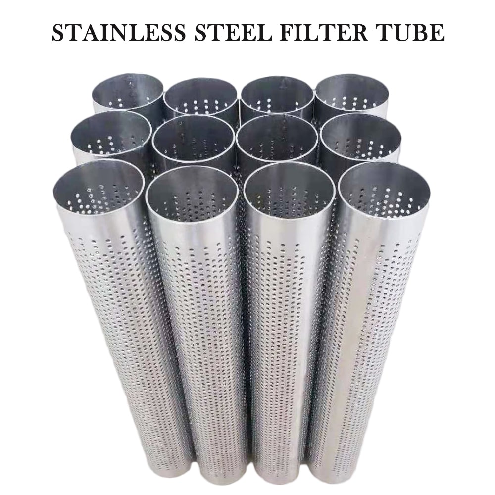
Formed perforated bodies showing cylindrical geometry and longitudinal seams.
Available End and Interface Configurations
Open ends
Core ends remain open for attachment to separately specified fittings.
Closed support end
A perforated or solid end may be integrated when shown on the drawing.
Flange or collar
A formed or welded interface locates the core within the element assembly.
Custom adapter
Threaded, stepped or drawing-specific components require full interface dimensions.
Open- and closed-end perforated supports for drawing-defined composite elements.
Define every finished interface
Show end margins, caps, collars, adapters, gasket seats and weld boundaries. Specify whether the quoted part is the bare support core or a completed assembly with filtration media.
Inside Support, Outside Support and Reverse Flow
Outside-to-inside flow
An internal core commonly supports media loaded inward.
Inside-to-outside flow
An external perforated cage commonly restrains media loaded outward.
Backwash or cycling
Reversed loading may require support on both sides or a revised attachment.
Carries the specified load and controls unsupported media span.
2. Drainage layer
Maintains a flow path and reduces direct contact with support openings.
3. Retention medium
Woven mesh, Dutch weave or sintered media defines the filtration requirement.
List the layer sequence from inside to outside and identify the function of each layer. For the four-way comparison of perforated, expanded, grid and coarse-mesh supports, see the filter element support core selection guide.
Real Maidong Perforated Support Components
These images show real Maidong cylindrical and composite metal-filter structures. They illustrate available fabrication forms only and do not claim a universal pressure rating or filtration performance.
Perforated cylindrical bodies used as structural cores in custom filter assemblies.
Perforated cylindrical cores
Formed perforated bodies showing cylindrical geometry and longitudinal seams.
Formed bodies and seams
Maidong examples of cylindrical media and support arrangements.
Media and support assemblies
Open- and closed-end perforated supports for drawing-defined composite elements.
Open and closed-end formats
Round-hole pattern illustrating hole diameter, pitch and ligament.
Controlled perforation pattern
Five-Step Support-Core RFQ
1. Send geometry
Provide the drawing, finished diameter, length, thickness and tolerances.
2. Define perforation
State hole, pitch, pattern, orientation and solid margins.
3. Detail joining
Show seam, end construction, weld scope and interfaces.
4. Mark loading
Give flow direction and normal, maximum and reverse differential pressure.
5. Complete the duty
Add medium, temperature, cleaning method, quantity and documents.
It is a formed perforated metal cylinder placed beside finer filter media to carry differential-pressure load, maintain shape and preserve a drainage path. Its holes are support openings, not automatically the filtration rating.
Provide finished OD and ID where controlled, length, wall thickness, hole size and shape, pitch and pattern, unperforated margins, seam, end details, roundness, straightness, tolerances and quantity.
Normally no. Woven mesh, Dutch weave, sintered mesh or another designated medium defines the retention requirement. Specify support perforation and filtration media separately.
Position depends on the direction of differential-pressure loading. Outside-to-inside flow commonly needs internal support; inside-to-outside flow commonly needs external restraint. Reverse-flow cases must also be stated.
State hole shape, hole size, pitch and pattern, then account for seams, overlaps, solid margins and end zones. Finished effective open area can be lower than theoretical sheet open area.
Maidong can review drawing-defined cylindrical support components. The RFQ should identify material, geometry, openings, seam, ends, layer relationship, operating medium, temperature and differential-pressure direction.
Request a Drawing-Based Support Core Review
Send the material, perforation, finished dimensions, seam, ends, layer relationship, flow direction, differential-pressure cases and quantity.