Perforated Metal Hole Size, Pitch and Ligament Guide
Perforated metal must be specified by more than hole diameter. A complete drawing identifies clear hole size, center-to-center pitch, straight or staggered pattern, ligament, orientation, sheet thickness, perforated zone, blank margins and tolerances before the sheet is formed into a filter component.
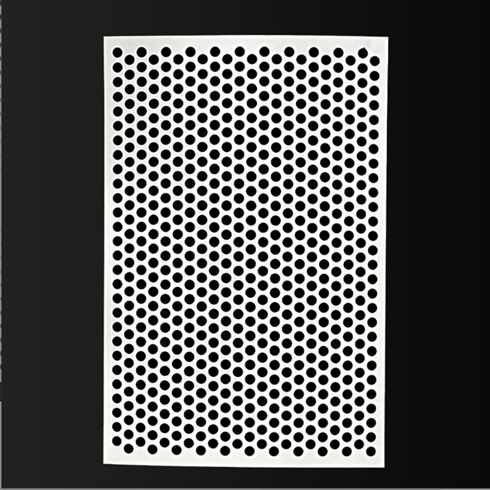
Round-hole perforation showing hole diameter, center pitch and the remaining metal ligament.
Direct Definitions
Hole size
The clear diameter or width of the opening, stated with shape and tolerance.
Pitch
Center-to-center spacing between adjacent holes in a stated direction.
Ligament
The remaining metal bridge between neighbouring hole edges.
Pattern and orientation
The row arrangement and its direction relative to the finished part or flow.
Perforated Metal Drawing Specification Table
Put dimensions and tolerances on one controlled drawing. If inspection is required, identify what is measured, where it is measured and the agreed sampling or acceptance method.
Drawing field
How to state it
Common ambiguity prevented
Hole shape and size
Round Ød, slot width × length, square side or drawing profile
Nominal designation without a measurable clear opening
Pitch
Center distance in each required direction
Confusing pitch with edge-to-edge bridge width
Pattern
Straight, 60° staggered or drawing-defined layout
Different open area and directional geometry
Sheet
Material, thickness, grain/rolling direction if critical
Assuming the same punching and forming behaviour
Perforated zone
Start/stop datums, blank margins and unperforated bands
Holes entering seams, bends, seals or mounting lands
Finished part
Cut size, bends, diameter, seam, flange and tolerances
Treating a flat sheet pattern as the complete component
Round-hole perforation showing hole diameter, center pitch and the remaining metal ligament.
Round-Hole Pitch and Ligament
For equal round holes measured along one pitch direction, the nominal metal bridge is ligament = pitch − hole diameter. This simple relation does not replace tolerance, burr, edge condition or forming review.
Use the perforated-metal open-area calculator for straight and staggered geometric open-area estimates. Finished filter open area will be lower when rims, seams, supports and blank margins mask the pattern.
Straight, Staggered and Directional Patterns
Straight rows
Hole centers align along principal directions; state both pitches if they differ.
Staggered rows
Rows are offset; identify the angle and reference direction on the drawing.
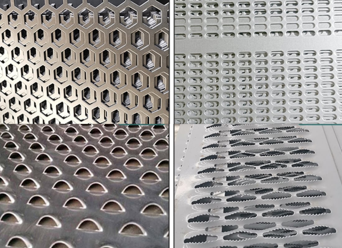
Slots and directional holes
State slot width, length, end form, row spacing and orientation to the part or flow.
Hole shape and orientation must be defined together with pitch and sheet direction.
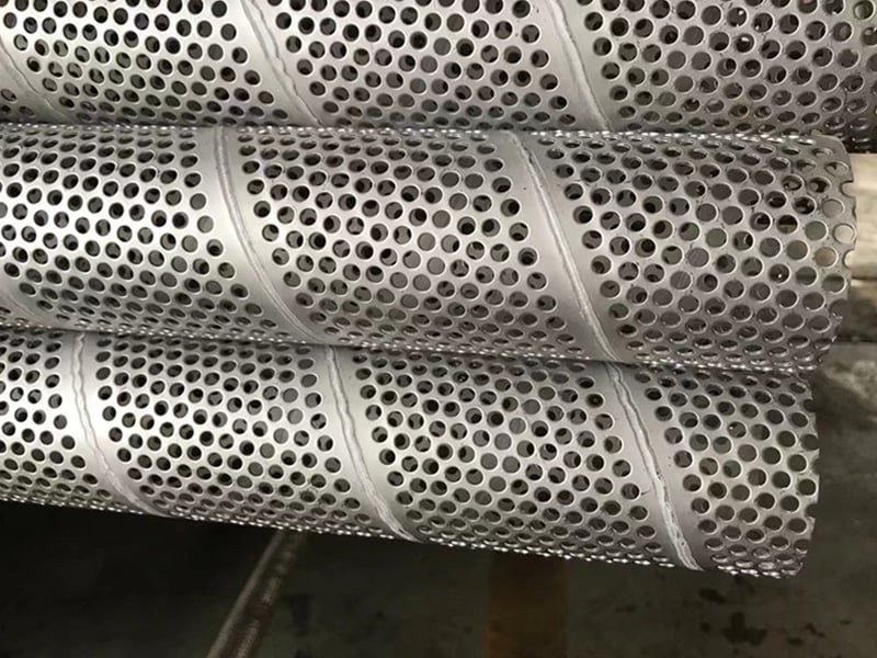
Orientation survives into the finished part
When a perforated sheet is rolled, bent or cut, the hole-row direction moves with the blank. Reference the pattern to the cylinder axis, bend line, flange or another finished-part datum whenever orientation matters.
Sheet Thickness and Perforation Feasibility
Hole-to-thickness relationship
Small holes in relatively thick sheet may require a different process or feasibility review.
Material behaviour
Alloy, hardness and finish influence punching, burr and distortion.
Pattern density
Small ligaments and high open area reduce remaining material between holes.
Part dimensions
Large sheets, narrow strips and edge margins respond differently during perforating and forming.
There is no single hole-to-thickness ratio that safely defines every alloy, hole shape, tolerance and production method. Submit the complete drawing for feasibility review before fixing a critical design.
Blank Margins, Seams and Forming Zones
Keep controlled unperforated areas where the part requires a weld seam, rolled rim, flange, gasket seat, mounting hole, bend or reinforcement. Dimension the perforated zone from stable datums instead of describing it only as “full perforation.”
Forming, seams and reinforcement create finished-part constraints beyond the flat perforation pattern.
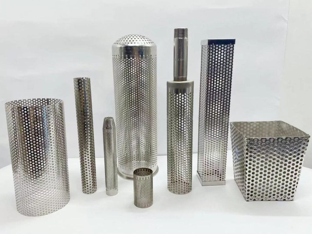
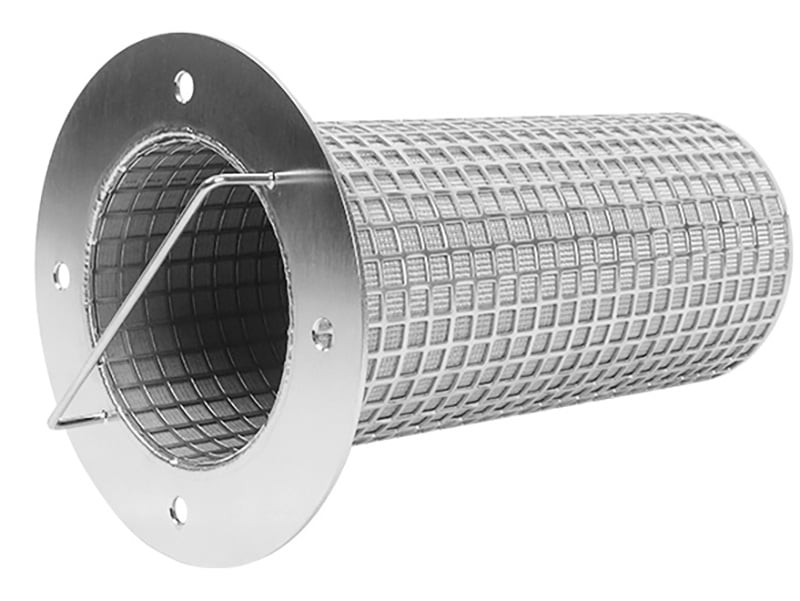
Real Maidong Perforated Filter Components
These real Maidong parts show how perforated zones interact with forming, rims, flanges, seams, supports and finished geometry. They are examples, not universal dimensional limits.
Round-hole perforation showing hole diameter, center pitch and the remaining metal ligament.
Round-hole pattern
Hole shape and orientation must be defined together with pitch and sheet direction.
Opening-shape options
Finished perforated filter components need margins, seams, forming datums and interface dimensions.
Fabricated filter forms
Flanges, blank margins, support grids and seams reduce the effective open area of a finished basket.
Flanged basket structure
Open Area, Strength and Filtration Are Different Questions
Geometric open area
Calculated from hole size, pitch and pattern before masked zones.
Structural behaviour
Depends on remaining metal, thickness, material, forming, supports and load.
Filtration opening
The perforated hole may be the coarse retention opening or only support finer mesh.
Finished pressure loss
Depends on area, thickness, layers, flow, fluid and contamination—not open area alone.
Ligament is the remaining metal between adjacent hole edges. For equal round holes along the measured pitch direction, nominal ligament equals center pitch minus hole diameter.
No. Also define pitch, pattern, orientation, sheet thickness, material, blank margins, part dimensions and tolerances. Different patterns can produce similar open area but different directional and fabrication behavior.
Thickness affects punching feasibility, hole quality, distortion, forming and strength. A hole-to-thickness combination should be reviewed for the actual material, pattern, part size and process rather than assumed from a universal ratio.
Straight rows align in both principal directions. Staggered rows are offset, commonly using a 60-degree layout for round holes. The drawing should identify the pattern and its orientation to the finished part.
Show material and thickness, hole shape and clear size, center pitch, pattern and orientation, perforated zone, blank margins, part dimensions, bends or forming, seam, interfaces, tolerances, quantity and inspection requirements.