
A perforated gas sparger tube introduces gas through discrete holes in a metal tube. Maidong can manufacture these components to customer drawings, with the tube geometry, hole layout, end construction and connection defined for your installation.
Specify the component and the duty together: gas and liquid, flow basis, available pressure, immersion depth, material, dimensions and the complete hole map.
Send OD or ID, wall thickness, overall length, active perforated length, straightness and dimensional tolerances.
Define hole size, count, axial spacing, angular position, blank zones and the required edge condition. Manufacturing method is reviewed against the drawing.
Show the inlet, closed or open end, thread or flange details, mounting points and removal clearance.
Scope boundary: this is a fabricated component supply enquiry, not a complete gas-distribution system design service. Process performance, distribution balance and installation suitability require the system owner’s validation. No standard stock range, pressure rating or delivery time is implied.
This is an RFQ checklist, not a catalogue of fixed sizes. Mark unknown items for review rather than assuming a standard hole size or tube rating.
| RFQ group | Information to provide | Why it matters |
|---|---|---|
| Gas and liquid | Composition, safety requirements, temperature and cleaning chemicals | Defines service and compatibility review. |
| Flow and pressure | Total and per-tube gas flow; actual/standard reference conditions; inlet pressure; vessel pressure; immersion depth | Allows the designer to assess outlet conditions and available pressure. |
| Tube dimensions | Material standard, OD/ID, wall, total length, active length and tolerances | Controls fit, strength review and fabrication. |
| Hole map | Diameter and tolerance, count, axial pitch, row positions, angular orientation and no-hole zones | Prevents an ambiguous instruction such as “holes evenly spaced”. |
| Ends and connections | Cap/closure, inlet, thread standard or flange drawing, sealing face, support and orientation | Defines assembly, leak boundary and installation. |
| Acceptance | Drawing revision, quantity, dimensional inspection, burr/finish requirements and any agreed test method | Separates requested checks from unverified performance promises. |
For reference-condition terminology, see actual versus standard gas flow. Attach your controlled drawing and tolerance checklist to the enquiry.

Specify the first-hole distance from a datum, the last-hole position, axial spacing and the angular direction of each row. Identify solid areas around the seam, end closures, supports and fittings.
For equal circular holes, total geometric outlet area is A = N × π × d² / 4, where N is hole count and d is hole diameter. Using d in mm gives A in mm². This is geometry only: it does not determine gas flow, pressure loss or distribution uniformity.
Equal holes along a tube do not automatically deliver equal flow. The system designer must consider the pressure distribution inside the tube and the conditions outside each outlet.
| Construction | Main role | Key specification |
|---|---|---|
| Perforated gas sparger tube | Discrete drawing-defined outlets release gas | Hole map, inlet conditions, immersion, connections and distribution validation. |
| Powder-sintered porous element | Gas passes through an interconnected porous wall | Porous grade, permeability, active area, wetting and process validation. |
| Perforated filter support tube | Rigid perforated body supports media or provides coarse screening | Open area, mechanical support, media attachment and retention duty. |
For the porous construction, view porous metal gas sparger elements. For filtration or media-support duty, use the existing perforated filter tube page. These are different duties, not interchangeable performance claims.
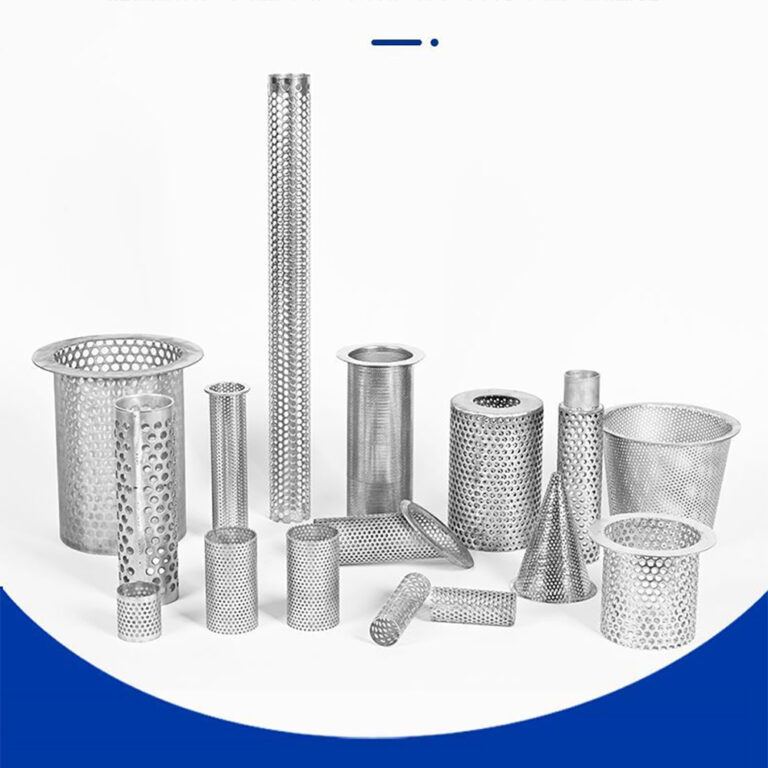
The Maidong library photographs on this page show related perforated metal fabrication and visible hole geometry. They are not customer sparging case studies and do not demonstrate bubble size or gas-transfer performance.
Show whether the far end is closed, removable or connected to another component. Define seam and closure requirements on the drawing.
Provide the exact thread standard, flange dimensions or mating drawing, including sealing and orientation requirements.
Specify the alloy, applicable material standard, weld finish, cleanliness and documentation requirements for review.
Use the end connection and sealing guide to prepare the interface details. Available fabrication is confirmed against the complete drawing, not from a photograph.
Provide liquid properties, operating level, minimum/maximum immersion and fouling tendency. Changing liquid head changes the pressure condition at an outlet.
Provide gas composition, flow reference, vessel conditions, orientation and manifold arrangement. Hazardous or oxygen service requires explicitly agreed design, cleanliness and safety requirements.
State the desired distribution result, test conditions, inspection access, cleaning method and replacement clearance. Hole size alone does not guarantee the process result.
Do not use a generic air-sparging component specification as a steam-injection design. Steam service introduces additional engineering and safety requirements and must be separately reviewed.
Describe the gas, liquid, flow, pressure, temperature and installed conditions.
Include dimensions, complete hole map, material, connections, tolerances and quantity.
Resolve unknowns and agree the fabrication scope, inspection requirements and quotation before production.
It is a metal tube with discrete openings that release gas into a surrounding liquid or process zone. Hole geometry, layout, supply pressure and installed conditions are specified for the intended duty. It is not the same construction as a powder-sintered porous diffuser.
Yes. Maidong can review and manufacture drawing-defined perforated or drilled metal tube components. Send the complete drawing, material, hole layout, connections, operating conditions and quantity. Manufacturing feasibility and acceptance requirements are agreed before production.
No. Bubble formation also depends on gas flow, liquid properties, wetting and operating conditions. A hole dimension is a fabrication requirement, not a guaranteed bubble-size specification.
Not necessarily. Pressure changes along the tube, immersion conditions and the complete manifold arrangement can affect outlet flow. Distribution uniformity requires system-level design and validation.
State the required alloy and material standard, together with the gas, liquid, temperature and cleaning exposure. Material suitability must be reviewed for the actual service; a stainless steel grade name alone does not establish compatibility.
Include the drawing revision, material, OD or ID, wall thickness, overall and active lengths, hole diameter and count, axial and angular layout, end closure, connection, weld and finish requirements, quantity, operating data and agreed inspection scope.
Send your tube drawing, hole map, material, operating data and required quantity to Maidong Metal Wire Mesh Products Co., Ltd. We will review the requested component fabrication scope with you.