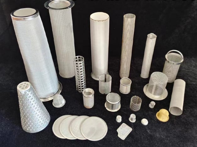
A filter element support core carries differential-pressure load and controls the unsupported span of fine media. Choose the core from load direction, opening geometry, effective open area, diameter, length, seam, interfaces and cleaning cycle. Do not use the support opening as the micron rating.
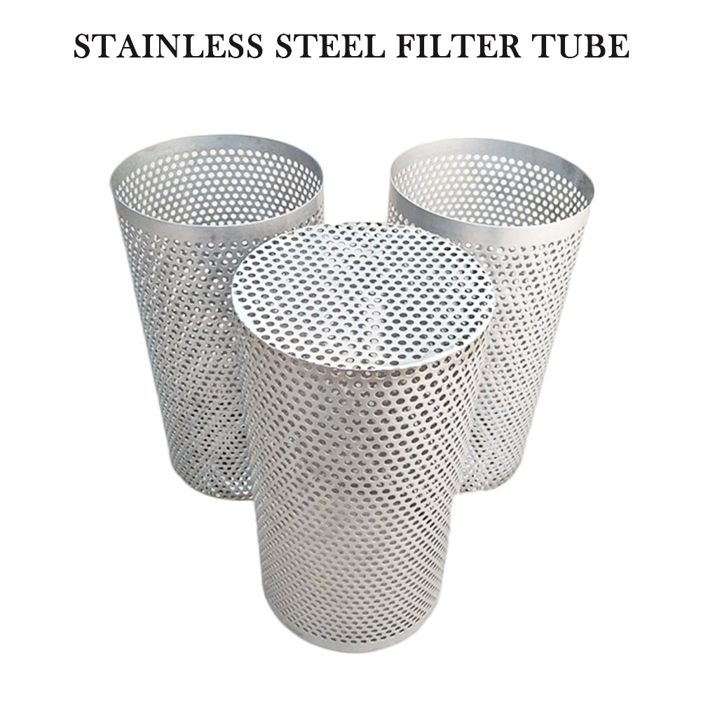
Perforated cylindrical bodies used as rigid support structures in filter assemblies.
Direct Answer: Separate Retention, Drainage and Structural Support
Retention layer
The fine mesh or porous medium controls the specified filtration characteristic.
Drainage layer
An open layer keeps a flow path beside the fine medium.
Support core
A rigid or semi-rigid structure carries the stated differential-pressure load.
Protective cage
An outer structure may protect media during handling or restrain outward loading.
Filter Support Core Comparison
No support type is universally best. Compare the actual geometry, load direction, open flow path, forming limits and media sensitivity.
Support type
Drawing fields
Useful characteristic
Review point
Perforated tube
Hole, pitch, pattern, thickness, margins, seam, ID/OD and length
Rigid cylindrical core with defined hole geometry
Solid margins and seam reduce effective area
Expanded metal
SWD, LWD, strand, thickness, orientation and formed diameter
Open cage with continuous strands
Raised strands and orientation affect media contact
Welded grid
Opening, both wire sizes, grid direction, seam and diameter
Repeatable open pattern and support lines
Crossings and projections affect fit and contact
Coarse woven mesh
Weave, mesh count, wire diameter, orientation and layer order
Relatively smooth backing beside fine cloth
More flexible than a rigid metal core
Perforated cylindrical bodies used as rigid support structures in filter assemblies.
Perforated Support Tube
Specify hole diameter or shape, pitch, pattern, wall thickness, unperforated margins, seam construction, finished diameter and length. Calculate open area from the actual pattern, then account for solid ends, overlaps and blocked regions.
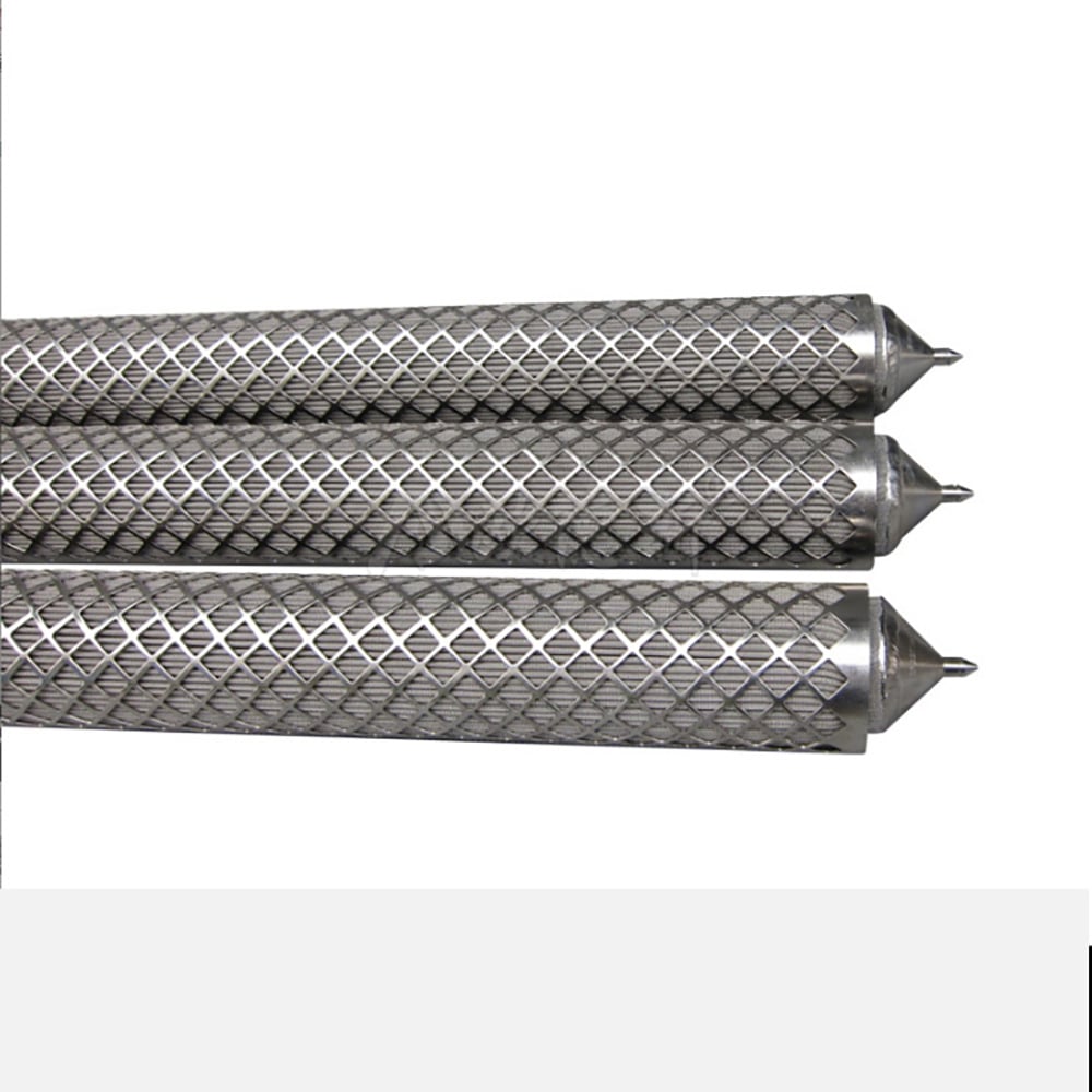
Define short-way and long-way diamond dimensions, strand width, material thickness, orientation, finished diameter and seam. The raised geometry can provide an open cage, but contact points and strand edges must be considered beside delicate fine media.
Expanded-metal cages provide open mechanical restraint around cylindrical media.
Welded Grid and Coarse-Mesh Supports
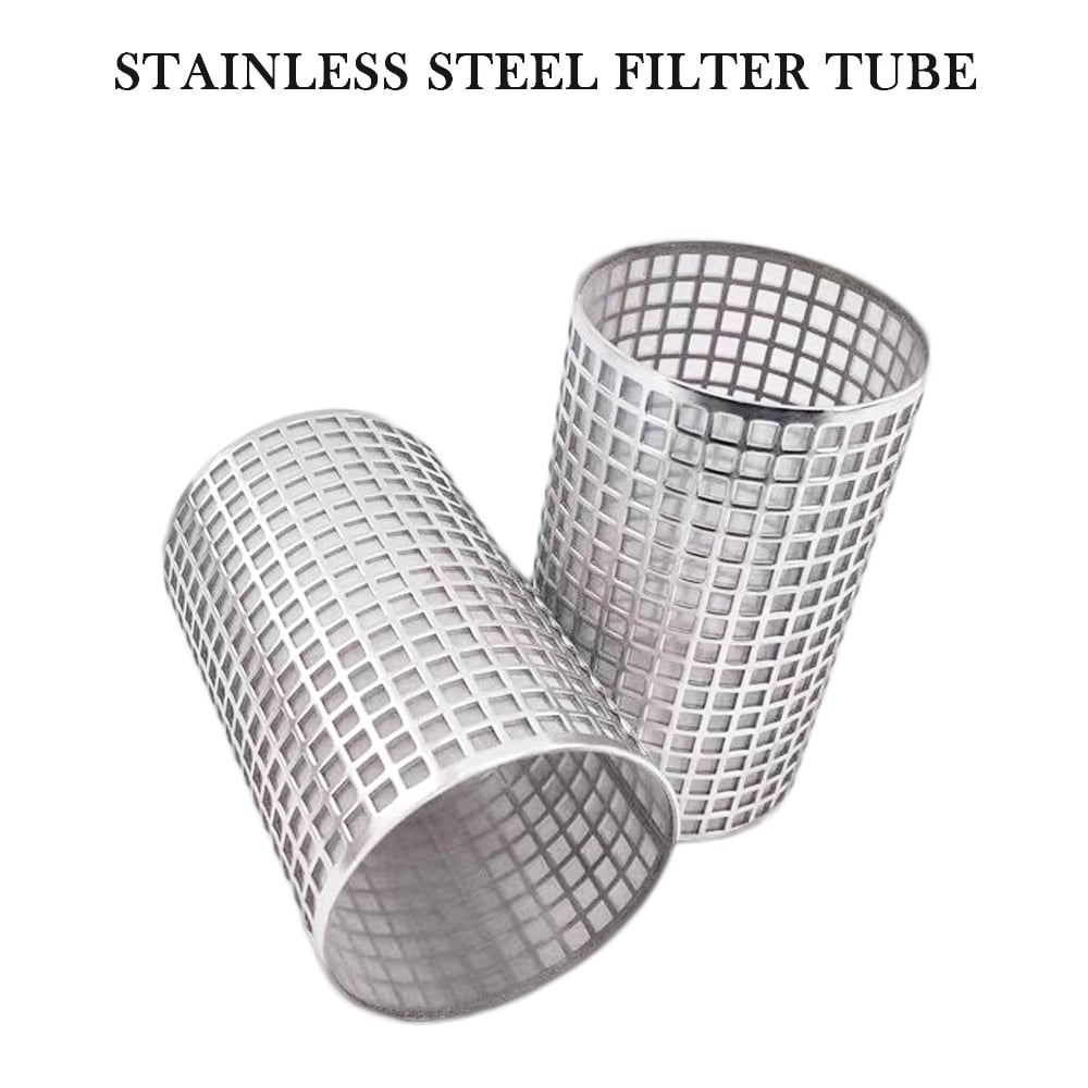
Open welded grids can support or protect cylindrical filter media.
Welded grid cage
Record both wire diameters, opening, grid direction, crossing profile, formed diameter and joint.
Open cylindrical supports must be specified independently from the retention layer.
Open mesh core
Record weave or wire layout, opening, wire size, orientation, diameter, seam and intended support function.
Support Position Follows Differential-Pressure Load
Outside → inside
Higher pressure outside commonly pushes the medium toward an internal core.
Inside → outside
Higher pressure inside commonly pushes the medium toward an external cage.
Reverse or cyclic flow
Backwash or transients may require restraint on both sides.
Flow arrows alone are not enough. State the higher-pressure side and the normal, maximum and reverse differential-pressure cases. Use the filter tube flow-direction guide for layer-position terminology and the differential-pressure guide for RFQ inputs.
Open Area, Support Span and Media Contact
Effective open area
Deduct seams, overlaps, solid ends and masked regions from theoretical pattern area.
Unsupported span
Opening size and layout determine the distance across which fine media carries local load.
Contact geometry
Sharp edges, raised strands or isolated contact lines can mark or concentrate load.
Drainage path
A separate drainage layer may be needed so the fine media does not seal against the core.
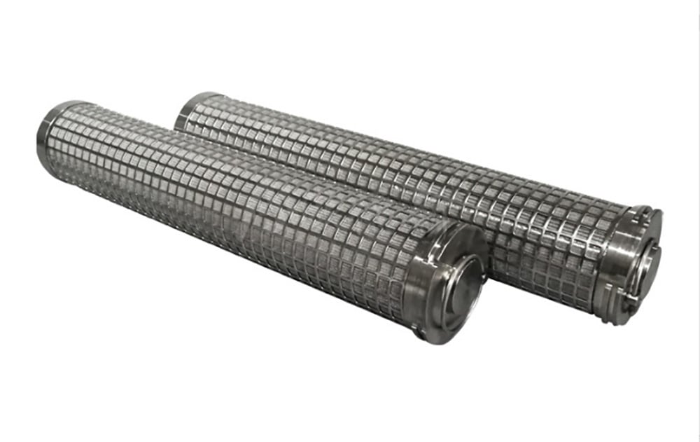
Real Maidong examples showing different media, support and cylindrical forms.
Layer Stack and Attachment
List the assembly from inside to outside and assign a function to every layer: support, drainage, retention or protection. State whether the layers are loose, wrapped, spot attached, edge joined, welded or otherwise retained.
ID/OD, length, wall or strand dimensions, roundness and straightness.
Opening pattern
Hole/pitch, diamond/strand or wire/opening with orientation.
Joint and ends
Longitudinal seam, end margins, caps, adapters and attachment boundaries.
Assembly relationship
Layer order, support side, media termination and critical finished diameter.
Real Maidong Filter Support Configurations
These real Maidong products illustrate perforated cores, expanded cages, welded grids and mixed cylindrical structures. They do not establish a universal pressure rating, open area or support capacity.
Perforated cylindrical bodies used as rigid support structures in filter assemblies.
Perforated cores
Expanded-metal cages provide open mechanical restraint around cylindrical media.
Expanded cages
Open welded grids can support or protect cylindrical filter media.
Welded grids
Real Maidong examples showing different media, support and cylindrical forms.
Mixed structures
Filter Element Support Core RFQ Checklist
1. Define the media
Identify the fine retention layer and rating basis.
2. Mark the load
Show flow plus normal, maximum and reverse differential pressure.
3. Specify the core
Provide type, opening geometry, material, diameter, length and seam.
4. Show the stack
List layer order, attachment, ends and critical interfaces.
5. Complete the duty
Add fluid, temperature, cleaning, quantity and drawing revision.
A support core is the load-carrying structure placed beside finer filter media. It can be a perforated tube, expanded metal, welded grid or coarse mesh cylinder, selected according to differential-pressure direction, unsupported span, geometry and flow requirements.
Normally no. The designated fine mesh or porous medium defines the retention specification. The support opening should be recorded separately so it is not mistaken for the filtration rating.
Place support on the side toward which the fine medium is loaded by differential pressure. Outside-to-inside flow commonly needs an internal core; inside-to-outside flow commonly needs external restraint. Reverse and transient loading must also be reviewed.
Provide the hole, pitch and pattern for perforated metal; SWD, LWD, strand and orientation for expanded metal; or wire and opening for grid or coarse mesh. Also account for seams, solid margins and blocked regions.
Include ID or OD, length, wall or material thickness, opening geometry, seam, roundness or straightness controls, ends, interfaces, layer order, flow direction and critical fit dimensions.
Not automatically. Backwash reverses loading and may require restraint on both sides, additional attachment or a different layer construction. State both normal and reverse differential-pressure conditions.
Need a Support-Core Structure Review?
Send the fine media, support-core drawing, layer order, flow direction, differential-pressure cases, dimensions, ends, cleaning method and quantity.