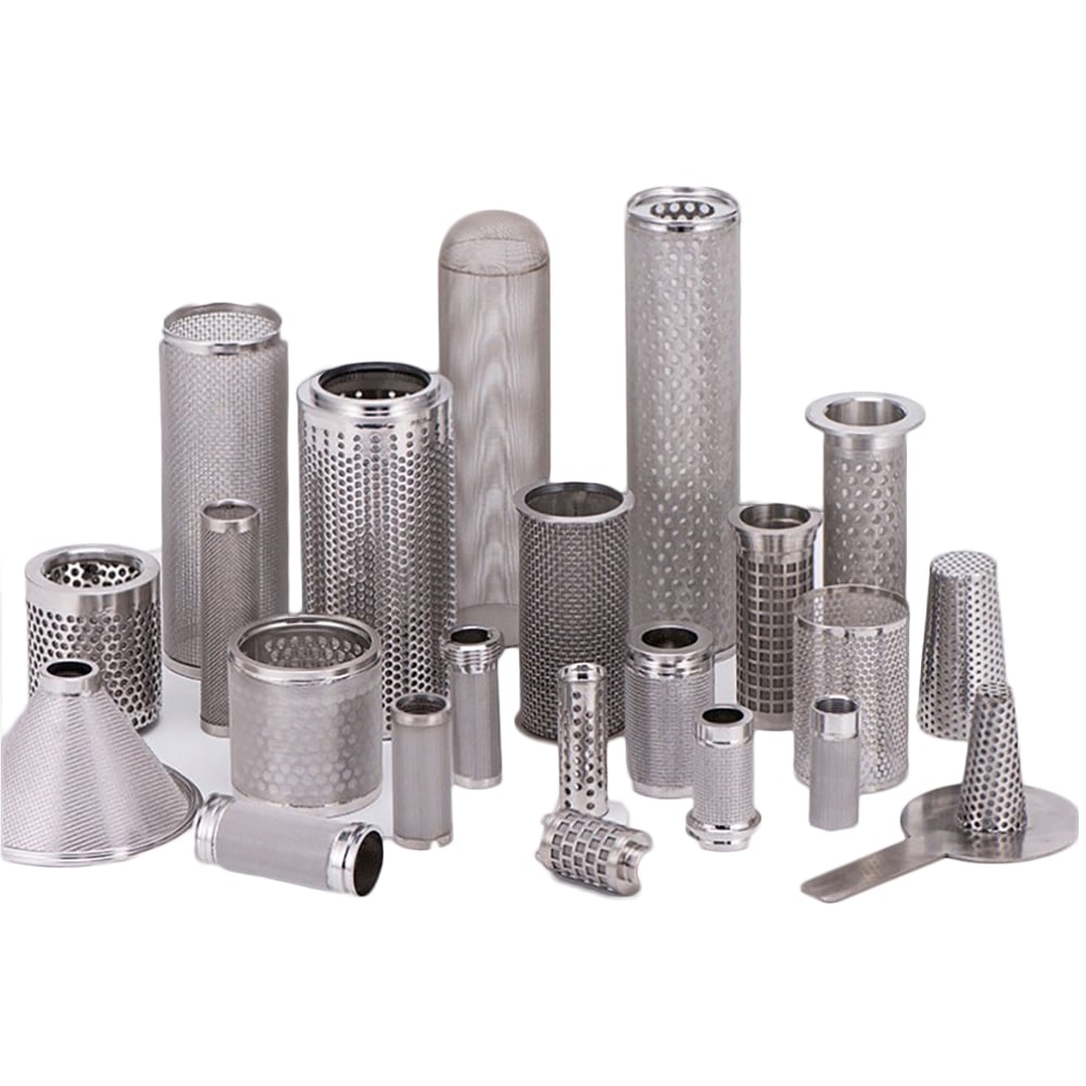
Differential Pressure Guide for Metal Filter Selection
Selecting a metal filter requires two different pressure checks: hydraulic resistance through the clean media and structural loading caused by differential pressure. State the fluid, flow, temperature, clean pressure drop, normal and maximum differential pressure, flow direction and reverse conditions on the same RFQ.
Filter media, support cage, joints and end connections must be reviewed for the stated differential pressure.
Direct Answer: Line Pressure, Pressure Drop and Differential Pressure Are Not Interchangeable
System line pressure
Absolute or gauge pressure at a system location; relevant to housings, joints and interfaces.
Clean pressure drop
Inlet-to-outlet loss through a clean element at a stated fluid, temperature and flow.
Operating differential pressure
Pressure difference across the element during normal contaminant loading.
Maximum / reverse differential
Highest stated load in normal, upset or reverse-flow direction.
Pressure Inputs Required in a Metal Filter RFQ
Every value needs its measurement condition. A pressure number without fluid, flow, temperature, direction and clean/loaded state cannot be compared reliably.
Pressure input
How to state it
Selection effect
Clean pressure drop
Value at named fluid, viscosity/temperature, flow and clean condition
Media permeability, area and geometry comparison
Normal differential pressure
Expected working range and flow direction
Support side and routine structural load
Maximum differential pressure
Limit, direction, duration and event condition
Media span, support, seam and end-load review
Reverse / backwash differential
Reverse limit, pulse or duration and cleaning sequence
Bidirectional support and layer retention
Line pressure
Operating and design pressure where relevant to the assembly
Housing interface, caps, joints and seals
Acceptance point
Allowed pressure drop, deformation, integrity or flow criterion
Creates a verifiable requirement
Fine filtration media and structural support perform different functions under pressure load.
Fine Media and Structural Support Have Different Jobs
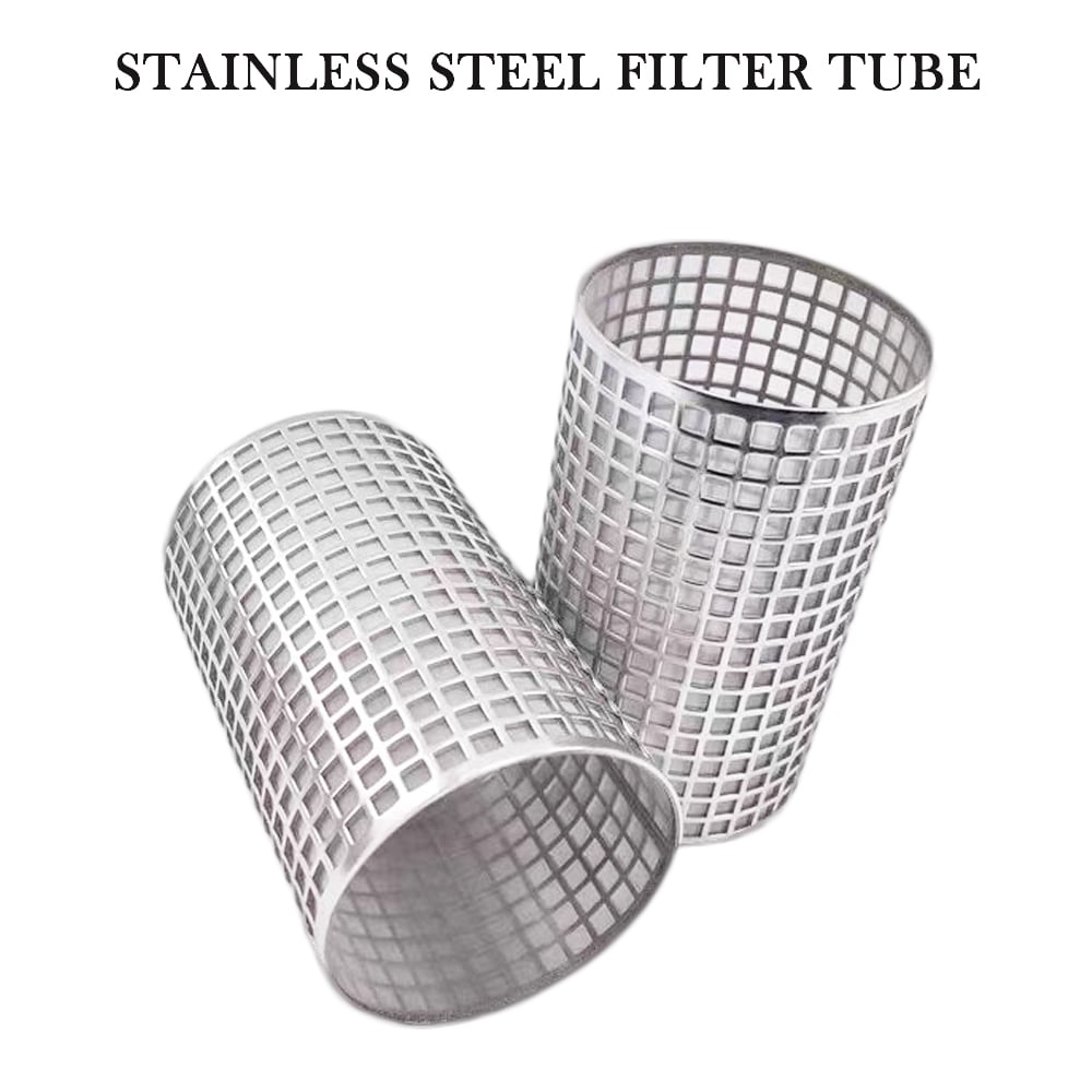
The woven mesh or porous layer controls retention and contributes flow resistance. A perforated tube, expanded metal or coarse mesh supports the fine media against pressure loading. Show layer order and which side sees higher pressure.
Viscosity, density, temperature and gas/liquid condition must be stated.
Media geometry
Aperture or pore structure, wire diameter, thickness and permeability affect resistance.
Effective area
Pleating and element dimensions change usable area, but supports and seals can mask part of it.
Contaminant loading
Pressure drop normally changes as material is retained; define the clean reference separately.
Clean Pressure Drop Test and Reporting Method
Measure a finished element as an installed flow component, not as an isolated mesh label. Use a clean element, a controlled fixture, stabilized test conditions and several flow points. Keep the upstream and downstream pressure taps fixed and far enough from local disturbances according to the agreed procedure.
Test field
Record
Why it matters
Test medium
Fluid or gas identity, composition, density and viscosity where relevant
Resistance changes with fluid properties
Temperature
Stabilized medium and element temperature at each test series
Especially important for liquid viscosity
Flow points
Actual mass or volume flow, reference conditions and stabilization rule
Creates a comparable pressure-drop curve
Pressure measurement
Upstream/downstream tap locations, instrument range, units and calibration status
Separates element loss from uncertain measurement geometry
Fixture correction
Empty fixture or bypass tube loss and whether it was subtracted
Prevents housing and piping loss being assigned to the element
Element condition
Clean/dry or wetted state, orientation, flow direction, seals and drawing revision
Defines the tested article and boundary
1. Baseline the fixture
Measure the empty fixture or a defined bypass tube over the same flow range.
2. Install the element
Use the specified seal, orientation, flow direction and assembly condition.
3. Stabilize each point
Record temperature, flow and inlet/outlet pressure only after the agreed stability rule.
4. Report the curve
Provide raw values, fixture correction, calculated element loss, units and drawing revision.
Structural capacity is not a property of “stainless steel mesh” alone. It depends on unsupported span, diameter, length, media layers, support geometry, seams, welds, end connections, material condition, temperature and direction of load.
Real Maidong Filter Examples: Pressure Duty Must Follow the Drawing
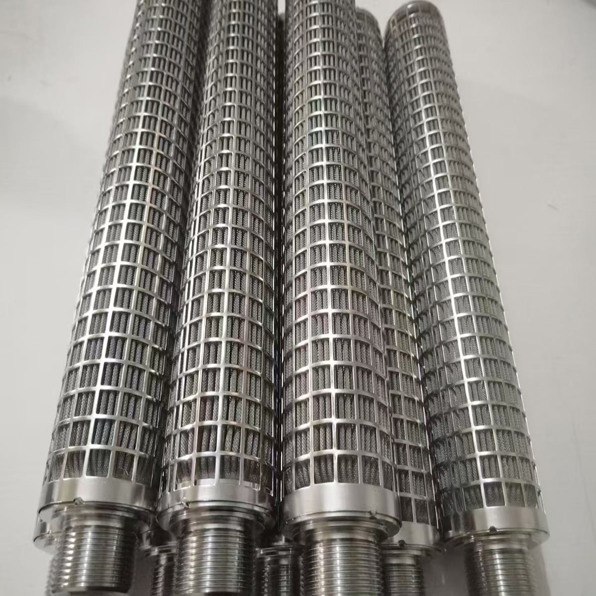
These are real Maidong filter forms, not universal pressure ratings. Each configuration needs its own media, support, seam, end and operating-duty review.
Filter media, support cage, joints and end connections must be reviewed for the stated differential pressure.
Supported cylindrical elements
Pleated area can affect clean pressure drop, while cores, cages and joints carry differential-pressure loads.
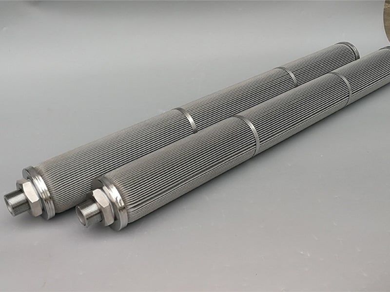
Pleated cartridge structures
Element diameter, length, media area and support geometry all influence pressure behavior.
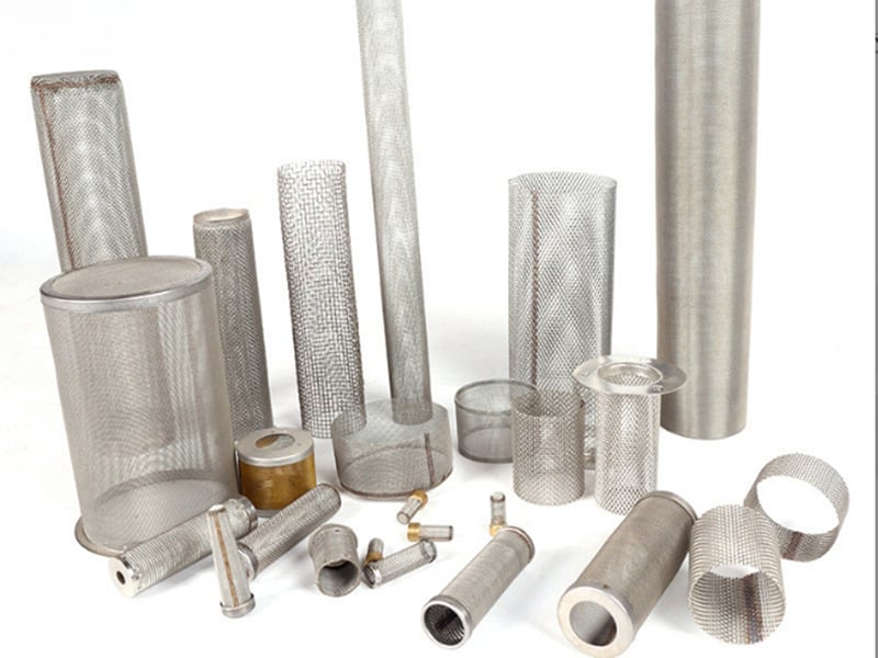
Mesh filter geometries
A pressure-duty RFQ must connect operating conditions to the exact element drawing.
Drawing-based configurations
Common RFQ Mistakes
Giving only line pressure
It does not state the load acting across the filter media.
Giving only a micron value
Retention does not define flow resistance or structural support.
Omitting reverse flow
Backwash can load the media from the unsupported side.
Using an unqualified pressure limit
Direction, duration, temperature and element condition are missing.
Metal Filter Differential-Pressure RFQ Checklist
1. Define the process
Fluid/gas, viscosity, temperature, contaminants and flow.
2. Define filtration
Particle target, aperture or rating and test basis.
3. State pressure conditions
Clean drop, normal/max differential, line and reverse pressure.
4. Mark the structure
Flow direction, media, layer order, supports, seams and ends.
5. Define acceptance
Dimensions, pressure/flow criterion, inspection, quantity and drawing revision.
Differential pressure is the pressure difference between the upstream and downstream sides of the filter element. It is not the same as the system line pressure, although both may be needed for the complete equipment review.
Clean pressure drop describes flow resistance through a clean element at stated fluid and flow conditions. Maximum differential pressure is the highest pressure difference the element is expected to withstand in the stated direction and condition.
Flow direction identifies which side of the fine media sees the higher pressure and where structural support is needed. Inside-to-outside and outside-to-inside loading can require different layer arrangements.
Yes, whenever reverse flow, pulse cleaning or backwashing can occur. State the reverse differential pressure and duration separately because the normal-flow support arrangement may not protect the media in reverse.
No. Allowable load depends on media, wire and opening, diameter, unsupported span, supports, seams, end connections, flow direction, temperature and fabrication. A mesh designation alone is insufficient.
Provide line pressure where relevant, clean inlet and outlet pressure or clean pressure drop, normal and maximum differential pressure, upset and reverse conditions, flow direction, duration, fluid, viscosity, temperature and flow rate.
Use a defined test fluid, temperature, stabilized flow points, calibrated upstream and downstream pressure measurements, the installed flow direction and the complete element fixture. Report whether empty-fixture pressure loss was measured and subtracted; do not compare values collected under different conditions as though they were equivalent.
Prepare a Pressure-Duty Filter RFQ
Send the fluid, flow, temperature, filtration target, clean pressure drop, differential-pressure conditions, flow direction, support, drawing and quantity for review.