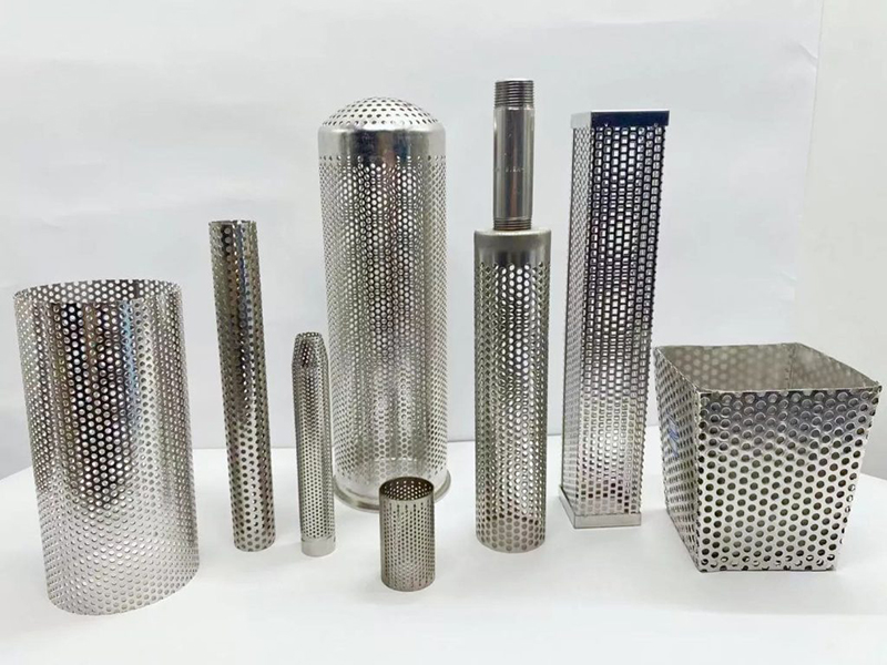
A welded filter tube is a formed mesh, perforated or composite cylindrical body whose longitudinal seam and attached ends are part of the finished specification. Define the media, joint location, finished diameter, roundness, support, end connections and operating duty together.
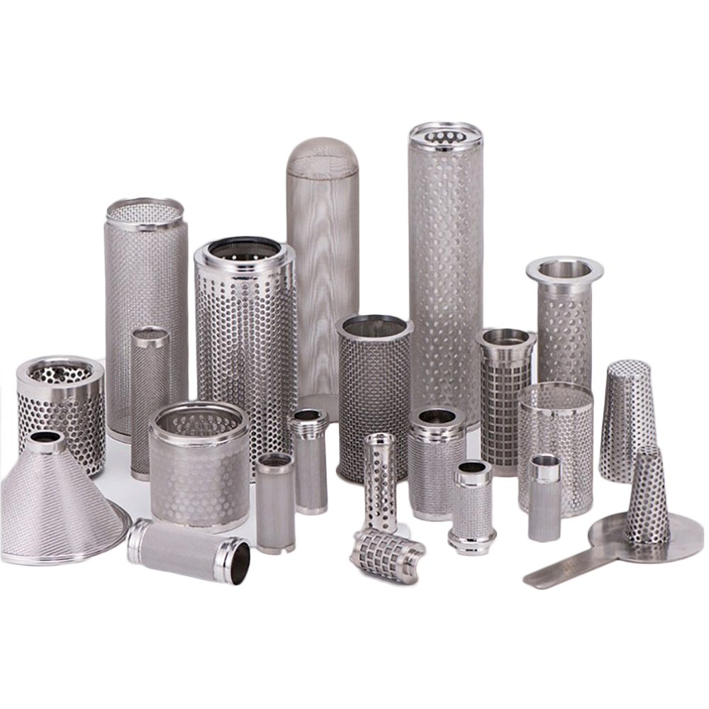
Drawing-specific cylindrical filter structures with different seams, bodies and end interfaces.
Welded Filter Tube Construction Scope
Longitudinal body seam
Joins the rolled mesh or sheet into a cylindrical body.
Media-to-support joint
Locates fine media against a perforated, grid or expanded support.
End attachment
Connects caps, collars, flanges, threaded fittings or sealing hardware.
Reinforcement joint
Attaches rings or frames used to control shape and support loading.
Welded Filter Tube RFQ Table
Welding method alone does not define an acceptable part. Quote from the finished drawing, including the seam profile, post-fabrication dimensions and the joint’s relationship to the active filter area.
Drawing field
What to specify
Why it matters
Filter body
Mesh/weave or perforation, wire/sheet thickness and material
Defines filtration or support function
Longitudinal joint
Location, butt/overlap arrangement, finished profile and continuity
Controls integrity, bypass risk and local obstruction
Finished geometry
OD/ID, length, roundness, straightness and end squareness
Controls equipment fit after forming and joining
Support and flow
Layer order, support side, flow direction and differential pressure
Places mechanical support on the loaded side
Ends and hardware
Caps, collars, flange, thread, seal faces and attachment details
Defines mounting, sealing and removal
Acceptance details
Critical dimensions and explicitly required checks
Aligns inspection with actual assembly risks
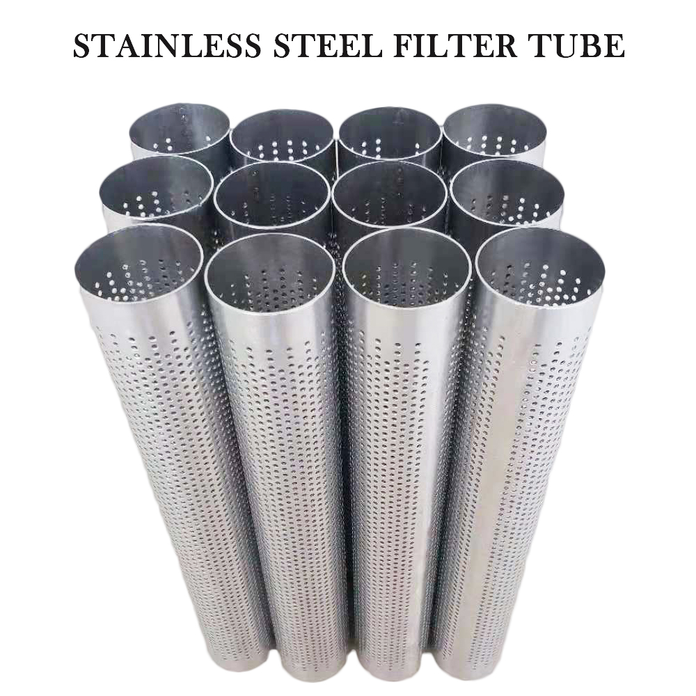
Perforated tube bodies formed from sheet with longitudinal joints.
Longitudinal Seam and Finished Geometry
Rolling and joining can influence roundness, straightness and the seam area. State whether OD or ID controls equipment fit, where the seam may be positioned and whether overlap is acceptable.
A welded tube may use woven mesh alone, perforated sheet alone or multiple layers. The coarse support does not automatically define the retention rating. State the fine medium separately and keep joint placement consistent with the required flow path.
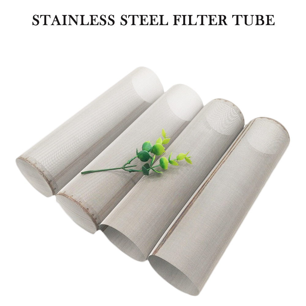
Wire mesh cylinders formed and joined into finished tube bodies.
Ends and Equipment Interfaces
Open tube
Joined cylindrical body supplied for integration into another assembly.
Closed end
Cap or formed closure attached according to the drawing.
Flange or collar
Locates, mounts or seals the tube in its housing.
Threaded fitting
Connection defined by thread standard, size and engagement.
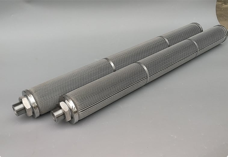
Finished filter elements showing longitudinal bodies, support rings and threaded interfaces.
Dimension the finished interface
Specify the mating dimensions, seal faces, end-face relationship and critical tolerances after welding. A reference photo can explain the concept but cannot replace the drawing.
These Maidong product images show representative cylindrical bodies, formed shapes, seams, support rings and finished connections. Final construction depends on the approved drawing.
Finished perforated components showing cylindrical seams and drawing-specific shapes.
Formed perforated structures
Perforated tube bodies formed from sheet with longitudinal joints.
Longitudinal tube seams
Finished filter elements showing longitudinal bodies, support rings and threaded interfaces.
Threaded finished elements
Welded Tube Review Workflow
1. Define the medium
State filtration body, support and material.
2. Locate the joints
Show seam, layer attachments and end welds.
3. Set finished geometry
Dimension OD/ID, length, roundness and ends.
4. Add operating load
State flow direction, pressure and service medium.
A welded filter tube is formed from wire mesh, perforated sheet or a multilayer structure and permanently joined along a longitudinal seam, at the ends or at attached hardware. The complete specification includes the filtration body, joint locations and equipment interfaces.
Identify seam position, joint style, overlap or butt arrangement where applicable, required finished profile, permitted distortion and any critical continuous or leak-path requirement. Do not rely only on the word welded.
The joint and heat-affected region can change local geometry, flatness, roundness or effective open area. The drawing should define whether the seam lies inside or outside the active filtration area and what finished condition is acceptable.
Yes, a fine mesh layer can be combined with a perforated or expanded support, but layer order, contact, attachment points, flow direction and differential-pressure loading must be defined.
Specify OD or ID, length, roundness, straightness, seam profile, end-face squareness, interface dimensions and critical tolerances after fabrication rather than only the dimensions of the flat blank.
Send the drawing, body material, filtration medium, support, seam and attachment requirements, finished dimensions, ends or fittings, flow direction, service conditions, quantity and any explicitly required inspection criteria.
Request a Welded Tube Drawing Review
Send the media, support, seam and joint details, finished dimensions, end connections, flow direction, operating duty and quantity.