A powder-sintered gas sparger element is a drawing-specific porous metal component used to introduce a defined gas flow into a liquid or process zone. Specify the gas, liquid, flow reference, target distribution, pore or permeability test basis, immersion depth, pressure loss, alloy, geometry, connection and cleaning method.
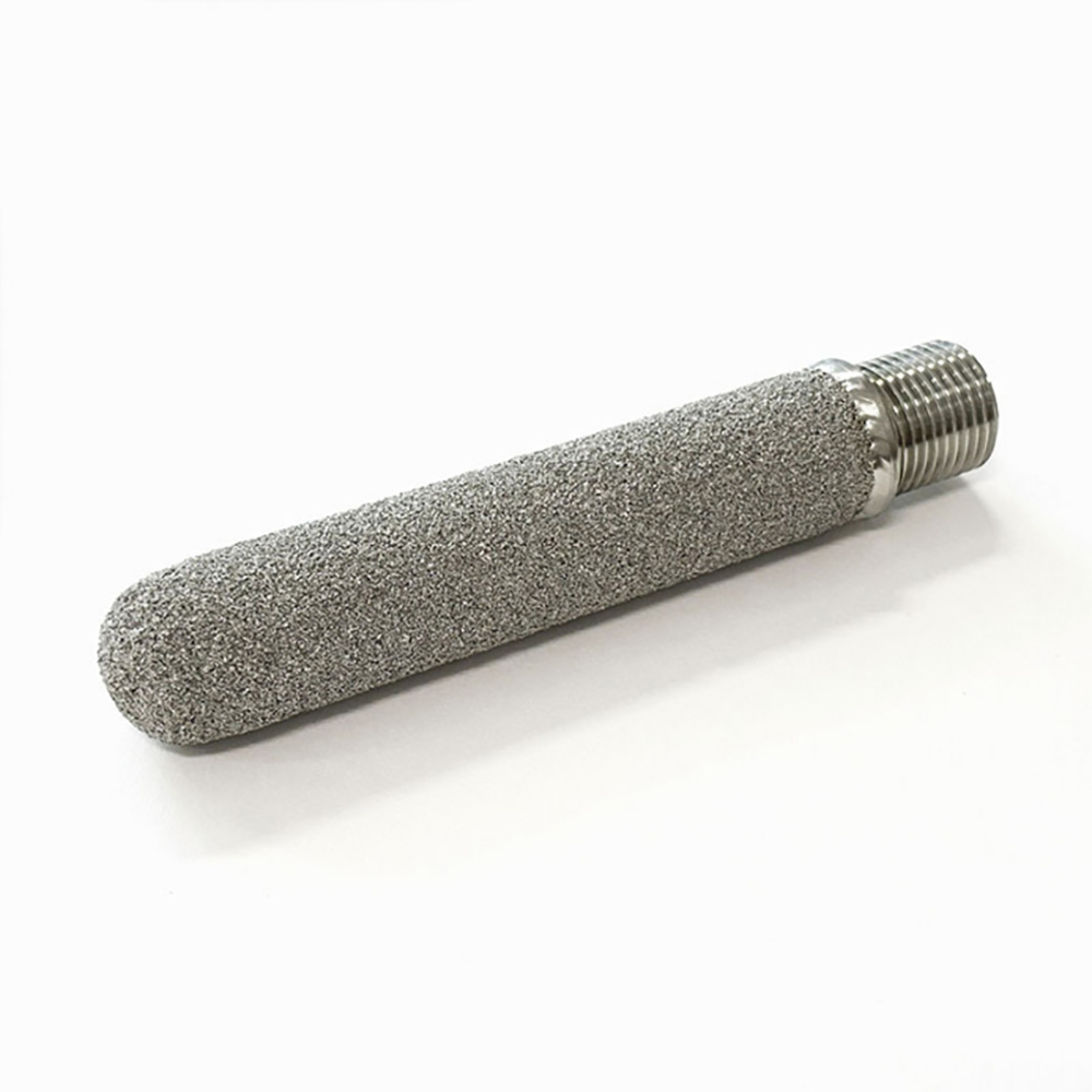
A threaded porous metal element illustrating cylindrical body and rounded closed-end construction.
Direct Answer: Define the Process Before the Porous Element
Gas duty
Composition, safety classification, flow basis, temperature and available inlet pressure.
Liquid duty
Composition, viscosity, density, surface condition, solids, temperature and fouling tendency.
Distribution target
Required process result, active length, orientation and acceptable variation or test method.
Installed component
Porous grade, dimensions, connection, sealing, immersion depth and cleaning access.
Component boundary: Maidong can review the porous element and drawing-defined interface. Vessel mixing, oxygen-transfer efficiency, reaction performance and complete distribution-system design require buyer or process-engineer validation.
Powder-Sintered Gas Sparger RFQ Matrix
A micron value and thread size are not enough. Put gas reference conditions, liquid head, porous test basis, pressure loss and the complete installed interface on one controlled RFQ.
RFQ group
Information to provide
Why it matters
Gas and flow
Composition, safety, total/per-element flow, actual/normal/standard basis and reference conditions
Defines comparable volumetric duty and material requirements
Liquid and immersion
Composition, viscosity, density, surface tension if known, temperature, pressure and immersion depth
Changes wetting, hydrostatic head and gas-release behavior
Porous requirement
Pore/rating or permeability basis, named test method, active area and target process result
Prevents unsupported pore-to-bubble assumptions
Pressure duty
Available inlet pressure, liquid head, clean element loss and maximum differential load
Connects flow to porous resistance and mechanical duty
Controls installation, leakage boundary and removal
Fouling and cleaning
Solids, precipitation, biological or resinous deposits, cleaning chemistry and acceptance checks
Links pore access and service cycle to real exposure
Different body lengths, diameters and connections must be controlled by an approved drawing.
Powder-Sintered Porous Structure
Metal powder particles are formed and bonded into a rigid body with interconnected flow paths. Unlike sintered woven mesh, the porous wall does not use identifiable woven layers. Specify the alloy, pore or filtration grade and test basis, permeability or flow requirement, wall build and finished geometry.
If your drawing specifies discrete holes in a fabricated tube, compare the perforated gas sparger tube. Identify whether the required component uses a porous wall or specified drilled/punched openings before requesting a quotation.
Pore Grade Is Not a Guaranteed Bubble Diameter
Pore distribution
A porous body contains a distribution of interconnected paths, not one isolated calibrated hole.
Wetting and surface
Liquid chemistry, surface condition and wetting affect gas release from the porous wall.
Gas velocity
Flow per unit active area changes pressure loss and the release pattern.
Liquid head
Immersion depth adds hydrostatic pressure that must be included in inlet-pressure calculations.
Ask for an agreed pore, permeability or flow-resistance test basis. A guaranteed bubble-size distribution requires an application-specific validation method supplied or approved by the system owner.
Gas Flow Basis, Liquid Head and Pressure Loss
State whether volumetric gas flow is actual, normal or standard and include reference temperature and pressure. Separate the liquid hydrostatic head from the clean porous-element pressure loss and any additional piping or manifold loss.
Introduces gas through a porous wall; complete oxygen-transfer performance is not implied.
Gas distribution component
Can form part of a buyer-designed distribution assembly; uniformity must be validated for that system.
Process contact
Gas and liquid chemistry, cleanliness and regulated-service requirements must be defined by the buyer.
Not a filtration claim
When operated as a sparger, the primary duty is gas passage into liquid rather than contaminant retention.
Real Maidong Porous Metal Element Examples
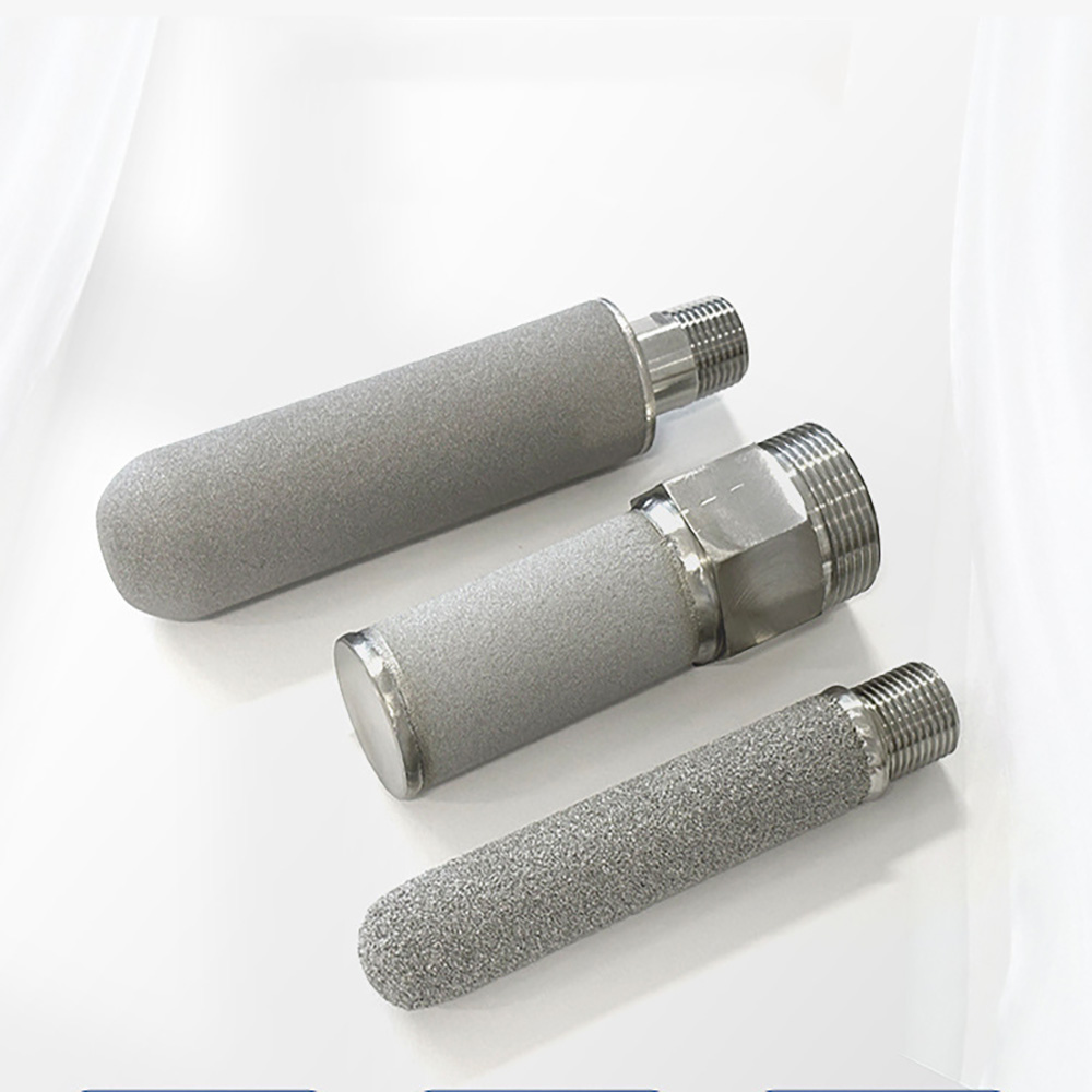
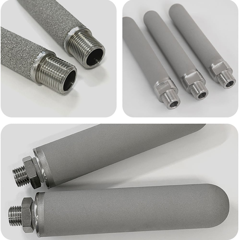
These real product images show powder-sintered cylindrical bodies and threaded interfaces. They demonstrate component forms only and do not establish bubble size, gas-distribution uniformity, transfer efficiency, chemical compatibility or pressure capacity without an approved specification.
A threaded porous metal element illustrating cylindrical body and rounded closed-end construction.
Single threaded porous element
Different body lengths, diameters and connections must be controlled by an approved drawing.
Different lengths and diameters
Connection and porous-surface examples for component-level gas distribution enquiries.
Thread and surface details
Different body lengths, diameters and connections must be controlled by an approved drawing.
Drawing-Controlled Component Options
Porous cylindrical or candle body
Rounded or drawing-defined closed end
Male thread, flange, collar or custom connection
Defined active and non-porous interface zones
Single element or buyer-designed manifold arrangement
Five-Step Gas Sparger Element RFQ
1. Define process
Gas, liquid, temperature, pressure, immersion and safety requirements.
2. Define flow
Total/per-element flow, reference basis, inlet pressure and liquid head.
3. Define porous duty
Pore/permeability test basis, active area and target process result.
4. Define component
Alloy, dimensions, wall, end, connection, seal, orientation and tolerances.
5. Define validation
Cleaning, dimensional checks, agreed tests, drawing revision and quantity.
It is a rigid porous metal component that passes a specified gas through an interconnected powder-sintered wall into a liquid or process zone. Maidong supplies the drawing-defined component; complete vessel mixing, oxygen-transfer or process performance remains the system designer’s responsibility.
No. Bubble formation also depends on pore distribution, wetting, surface condition, gas flow, liquid properties, immersion depth, pressure and element orientation. State the required result and test basis without assuming a one-to-one pore-to-bubble relationship.
Provide full gas composition and safety classification, liquid composition, viscosity, density, surface tension where available, solids or fouling tendency, temperature, pressure, immersion depth and cleaning exposure.
State total and per-element gas flow, whether volumetric flow is actual, normal or standard, reference temperature and pressure, liquid head, available inlet pressure and acceptable element pressure loss at the named condition.
Cleaning suitability depends on deposited material, porous grade, alloy, joint and connection. State cleaning chemistry, temperature, direction, pressure and acceptance checks; do not assume that every fouled pore network can be fully restored.
Request a Porous Sparger Element Review
Send the gas and liquid data, flow reference, immersion depth, available pressure, target result and test basis, porous grade, dimensions, connection, seal, cleaning method, drawing revision and quantity.