Gas Filter Actual vs Standard Flow Rate Guide & Calculator
Gas volumetric flow changes with pressure and temperature. Before comparing filter pressure drop, identify whether flow is mass, standard/normal volume or actual volume, state the reference temperature and absolute pressure, and keep gas composition and test conditions aligned.
Finished gas-filter elements require a stated gas condition and flow basis before pressure drop can be compared.
Direct Answer: Standard and Actual Volume Are Different
Mass flow
Gas mass per unit time; not changed by choosing a volumetric reference.
Reference volume
Volume converted to a named temperature and absolute pressure.
Actual volume
Volume occupying the filter at its operating pressure and temperature.
Pressure-drop datum
ΔP tied to gas, flow basis, temperature, pressure, element and condition.
Never submit only “100 Nm³/h” or “100 SCFM” without the reference definition. Conventions vary by company, standard and region.
Gas Flow Reference-to-Actual Calculator
Enter one reference volumetric flow, its reference condition and the actual filter-inlet condition. The output keeps the same volume/time unit as the input.
Actual flow: 23.22 (same volumetric unit/time)
Uses Qactual = Qreference × (Preference / Pactual) × (Tactual,K / Treference,K) × (Zactual / Zreference). Use absolute pressure and Kelvin. This is an ideal-gas-based conversion aid, not a pressure-drop or equipment-safety calculation.
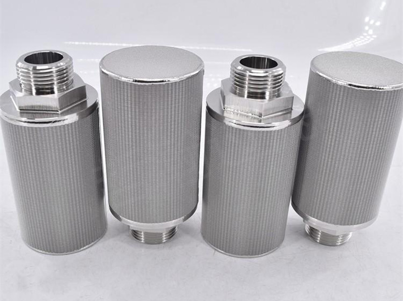
Threaded filter formats with different ends and active lengths.
Conversion Equation and Required Units
For the same molar flow, Qactual = Qreference × (Preference / Pactual) × (Tactual / Treference) × (Zactual / Zreference). Temperature must be absolute (Kelvin) and pressure must be absolute. Set the Z ratio to 1 only when the ideal-gas approximation is acceptable for the purpose.
Gauge pressure is not absolute pressure. Convert it using the specified atmospheric reference before calculation. For high-pressure or non-ideal service, obtain suitable compressibility/property data.
Gas Filter Flow-Basis Comparison Table
Flow statement
Minimum definition
Common error
Mass flow
Mass/time, gas composition and operating state
Treating mass flow as a volumetric value
Normal / standard volume
Volume/time plus exact reference T, absolute P and standard name
Assuming N and S use one worldwide definition
Actual volume
Volume/time at named actual T and absolute P
Using line gauge pressure directly
Filter ΔP
Gas, composition, flow basis, T, P, clean/loaded state and exact element
Comparing values measured under different conditions
Worked Example: Reference Flow to Actual Inlet Flow
Reference flow
100 volume units/hour at 0°C and 101.325 kPa abs.
Actual condition
40°C and 500 kPa abs at the filter inlet.
Z ratio
Assume 1.0 only for this illustrative calculation.
Result
Approximately 23.22 actual volume units/hour.
The smaller actual volume does not mean the filter pressure drop is automatically lower by the same ratio. Gas density, viscosity, velocity through the effective media area and the complete porous construction still matter.
How to Compare Gas-Filter Pressure-Drop Data
Use the same gas or a documented comparable test gas; align inlet pressure, temperature, flow basis, element geometry, active area, media construction and clean or loaded state. Record whether ΔP belongs to a media coupon, clean element or complete housing assembly.
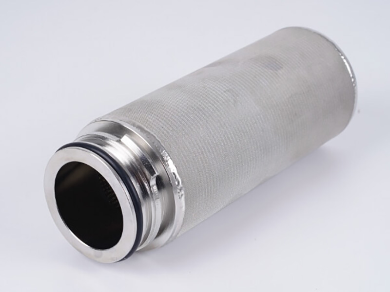
The complete element includes media, active area, support, ends and sealing interface.
Gas Composition, Compressibility and Condensation
Composition
List every relevant constituent rather than writing only air or gas.
Compressibility
Use a defensible Z basis when non-ideal behavior matters.
Condensation
Aerosol or liquid formation changes the filtration duty and pressure behavior.
Safety boundary
Special, reactive, flammable or hazardous service requires project-specific review.
This calculator does not evaluate phase behavior, dew point, chemical compatibility, ignition risk, emissions compliance or housing design. For mechanical filtration context, see industrial gas filtration wire mesh.
Real Maidong Gas-Filter Element Forms
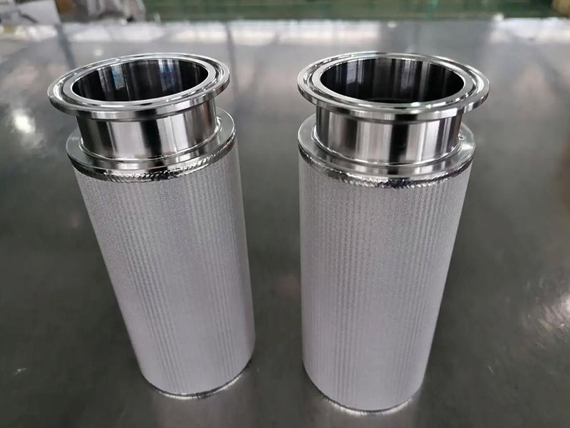
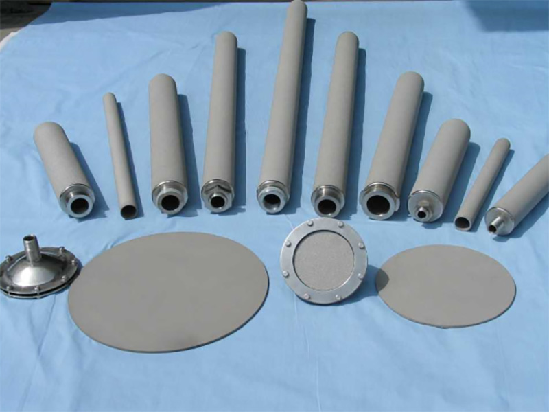
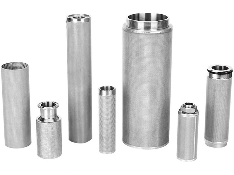
These real elements show changes in diameter, active length, ends and connections. Images do not establish flow capacity, rating or pressure drop without a controlled specification.
Finished gas-filter elements require a stated gas condition and flow basis before pressure drop can be compared.
Clamp-connected elements
Active area and geometry remain separate from the gas-flow reference condition.
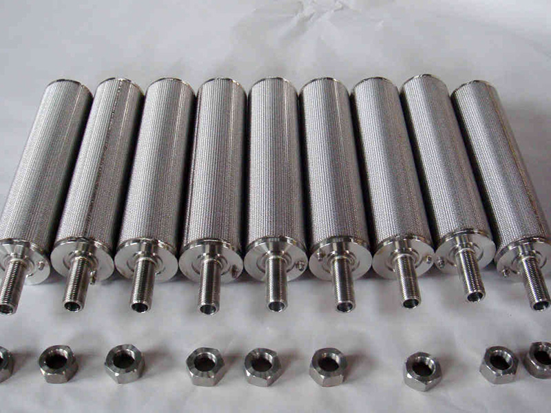
Long cartridge series
Different porous forms cannot share one pressure-drop value without aligned test conditions.
Porous form comparison
Element size and connection options illustrate why flow data must be tied to the exact drawing.
Size and connection range
Threaded filter formats with different ends and active lengths.
Threaded element formats
The complete element includes media, active area, support, ends and sealing interface.
Single finished element
Gas Filter Flow and Pressure-Drop RFQ Checklist
1. Define gas
Composition, moisture/condensables and safety classification.
2. Define flow
Mass or volume; reference/actual T and absolute P; Z basis.
3. Define filtration
Particles/aerosols, rating basis, media and effective area.
4. Define pressure
Line pressure, clean/loaded ΔP, maximum and reverse duty.
5. Define element
Drawing, layers, dimensions, ends, seals, test and acceptance.
Actual volumetric flow is the volume passing the filter at the named operating pressure and temperature. It should be paired with gas composition and whether the pressure is absolute or gauge.
It is a volumetric flow referred to a stated reference temperature and absolute pressure. The words standard and normal do not identify one universal reference; always state the actual values and units.
Gas volume relates to thermodynamic pressure measured from vacuum. Gauge pressure must be converted to absolute pressure using the applicable local or specified atmospheric reference.
No. The conversion only aligns volumetric conditions for the same gas quantity. Pressure drop also depends on composition, density, viscosity, media, active area, geometry and clean or loaded condition.
Review a qualified gas property method when pressure is high, the gas is non-ideal, composition varies, condensation is possible or accurate compressibility data is required.
Provide mass flow or volumetric flow, the reference or actual temperature and absolute pressure, gas composition, compressibility basis if used, clean and loaded pressure-drop limits, element area, geometry and drawing.
Prepare Comparable Gas-Filter Data
Send gas composition, mass or volumetric flow basis, exact reference and operating conditions, particle duty, clean/loaded pressure-drop limits, element geometry, active area and drawing.