
Perforated Filter Panels with Solid Margins
Send Maidong your perforated filter panel drawing with the active hole zone and solid mounting margins defined. Include the finished outline, border widths, fixing-hole coordinates and sheet specification.
The enquiry should distinguish repeating filtration holes from installation features. Specify any frame, fold, seal or attached mesh layer separately.
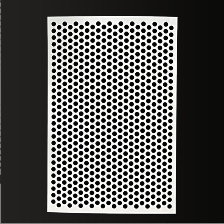
Define the Border as a Functional Feature
Use the solid margin to describe the region reserved for your mounting or clamping arrangement. Identify where fasteners, seals or supporting members contact the panel and which areas must remain free of the filtration pattern.
For standard repeating hole-pattern information, see round-hole perforated metal. This page concerns a finished panel with controlled blank regions and installation features.
Dimension the Outline, Hole Zone and Fixings
Choose drawing datums and locate the panel edges, hole-zone boundaries and fixing-hole centres from those references. Give border widths on each side when they differ. A single overall length and width does not define the pattern position.
State whether the border is measured to the first hole edge, its centre or another identified reference. Keep this interpretation consistent with the required pattern and manufacturing review.
Prepare a Complete Panel Specification
| Panel material | Material designation, sheet thickness and required material records. |
|---|---|
| Finished outline | Length, width, profile details and dimensional tolerances. |
| Perforation | Hole shape/size, pitch, arrangement and pattern orientation. |
| Solid zones | Border dimensions, internal blank areas and datum references. |
| Pattern termination | Complete or permitted partial holes at boundaries; first-row position. |
| Mounting features | Fixing holes, slots or countersinks if required, located independently. |
| Installation | Support, clamping, contact faces and intended flow direction. |
| Finishing | Cut-edge and hole-edge requirements, flatness and any forming. |
| Order and checks | Drawing revision, quantity, inspection conditions and trial-fit requirements. |
If the panel must fit an existing holder, include the mating drawing. Mark sample measurements separately from the required acceptance limits, especially if the sample is worn or distorted.
Keep Pattern and Mounting Holes Separate
A fixing hole is an independently located feature, not simply a selected hole in the repeating pattern unless your drawing explicitly defines it that way. Show slot direction, clearance and other mounting details individually.
If different perforation zones are required, define each zone and its boundary. Confirm whether partial holes are acceptable at the edge and identify blank areas that must remain intact.
Use the hole size, pitch and ligament guide when describing the repeating pattern.
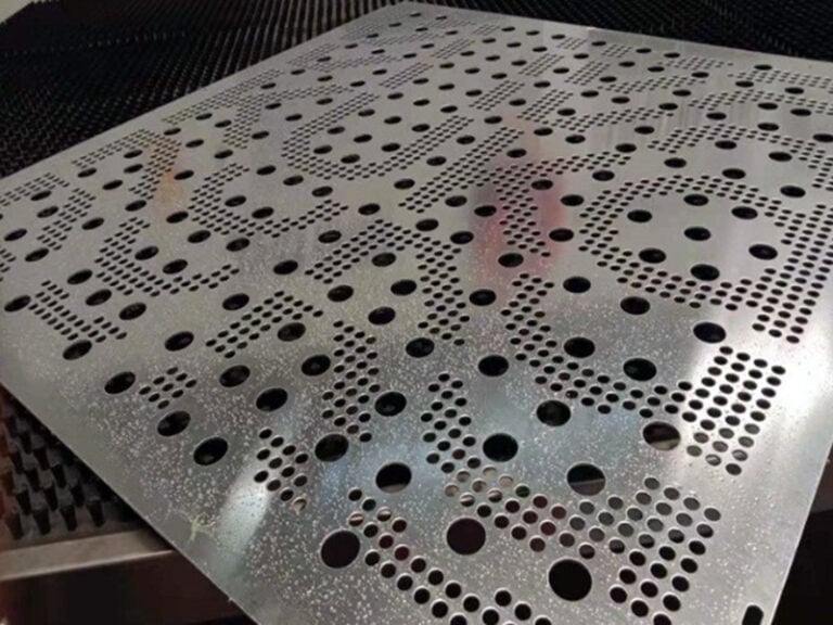
Perforated Sheet Punching Reference
Process reference: sheet perforation beneath a press tool, with a perforated region beside unperforated material. This silent excerpt illustrates hole production, not a finished panel to your drawing. Material, hole dimensions, border width and acceptance requirements need separate confirmation. Source: user-supplied video collection; factory ownership is unverified. It is not presented as Maidong factory footage.
Use the Correct Area and Support Basis
The open-area percentage within a repeating hole field differs from the open area relative to the whole panel when borders and blank regions are present. State the required calculation basis and identify any area covered by clamps or other parts.
Solid margins do not independently establish pressure capacity, stiffness or sealing. Provide the support layout, loading and acceptance criteria for review. If a woven layer and backplate are supplied together, see woven mesh panels with perforated backing.
English Enquiry Template
Please quote perforated filter panels with solid margins to drawing [number/revision], quantity [ ].
Material and thickness [ ]. Finished outline and datums [ ]. Hole size, pitch and hole-zone boundaries [ ]. Border widths and partial-hole policy [ ].
Fixing holes/slots, support and contact faces [ ]. Edge, flatness and inspection requirements [ ]. Please identify missing information and proposed layout exceptions.
Solid-Margin Panel FAQ
It is a specified area without the filtration hole pattern, often retained for mounting or clamping. Separately drawn fixing holes may still be present in that border.
No. Dimension each required border or use an explicit symmetric note. Do not assume equal margins from a photograph.
Give hole sizes and centres from named drawing datums. Keep mounting holes distinct from the repeating perforation pattern.
No. Unperforated borders and other blank zones reduce the perforated area relative to the complete panel. State which area basis is being used.
State whether partial holes are permitted and define how the pattern terminates. Confirm the proposed layout against the required margin.
Only if separately specified and confirmed. A solid border alone does not constitute a frame, a seal or a load rating.
Request a Drawing-Based Quotation
Send the hole layout and installation details. Feasibility, scope, price and delivery are confirmed after review.