MACHINING COOLANT SOLIDS COLLECTION · MADE TO DRAWING
Machine Tool Coolant Filter Basket
A machine tool coolant filter basket is a removable stainless steel insert used to collect chips and specified particles at a sump, return, pump inlet or equipment opening. Specify the installation boundary, chip load, coolant, opening, liner, flow, support, handle, drainage and cleaning access together.
Choose perforation, woven liner or composite support from retention and flow needs.
Operator access
Dimension the handle, lifting direction, drainage and space needed to empty and clean the basket.
Coolant Filter Basket Specification Table
Basket length and mesh count alone cannot define a reliable replacement. Include the machine interface, chip behaviour, coolant circuit and maintenance method.
Mobile: swipe sideways to view every column.
RFQ group
Information to provide
Function controlled
Installation
Opening, seat, rim/flange, depth, orientation, clearance and removal path
Fit, stability and bypass boundary
Contamination
Chip material, shape, size range, loading and abrasive fines
Opening, basket volume and cleaning frequency
Coolant duty
Water-miscible or oil-based fluid, concentration information, temperature and viscosity where relevant
Material, flow and cleaning review
Filter medium
Hole or mesh opening, wire, layer order, support and liner attachment
Retention, drainage and structural stability
Hydraulics
Flow direction/rate, liquid head or differential pressure and allowable level change
Active area and overflow risk review
Maintenance
Handle, loaded removal, drainage, emptying, cleaning, quantity and drawing revision
Practical service and repeatable replacement
The flange, seating boundary, liner and handle must follow the machine or coolant-tank interface.
Sump, Return or Pump-Inlet Interface
Show where coolant enters and leaves, how the basket is supported, the installed depth, seating face, rim or flange, clearance to nearby parts and the direction of removal. Identify any gap that could allow chips to bypass the screen.
The industrial tank filter basket page provides broader tank-interface terminology; this page remains focused on machining coolant service.
Perforated Basket, Mesh Liner or Composite Structure
Perforated body
Coarse chip collection or rigid support defined by hole, pitch, pattern and margins.
Woven mesh liner
Smaller defined opening attached to control bypass at rims, seams and joints.
Composite basket
Fine mesh supported by perforated sheet, expanded metal or heavier mesh.
Select the Opening from Chip Geometry and Protected Equipment
Long curls, flat chips, short fragments and grinding fines do not behave like equal-diameter spheres. State the dimensions and shapes that must be retained and what downstream pump, nozzle or passage needs protection.
Fine media may need perforated or expanded support for flow, handling and pressure conditions.
Handle, Drainage and Cleaning Access
The handle must fit the available lifting path and remain accessible after chip loading. Define whether coolant must drain before removal, how collected chips are emptied and whether the liner can be reached without damaging it.
Cleanability depends on the chip and coolant, media, joints and approved maintenance method. Do not assign an unsupported service interval or reusable life.
Typical Machine-Tool Installation Points
Coolant sump opening
Drop-in basket collecting chips before recirculation.
Return channel
Removable screen intercepting debris returning from the machining zone.
Pump inlet protection
Basket matched to the inlet geometry and allowable hydraulic restriction.
Central coolant stage
Coarse removable element used before another treatment or fine-filtration stage.
Real Maidong Coolant Basket and Mesh Configurations
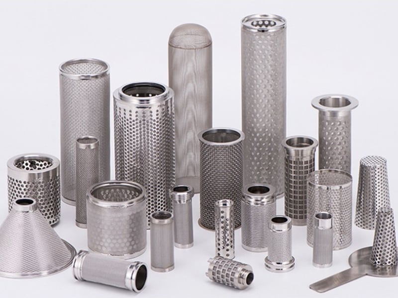
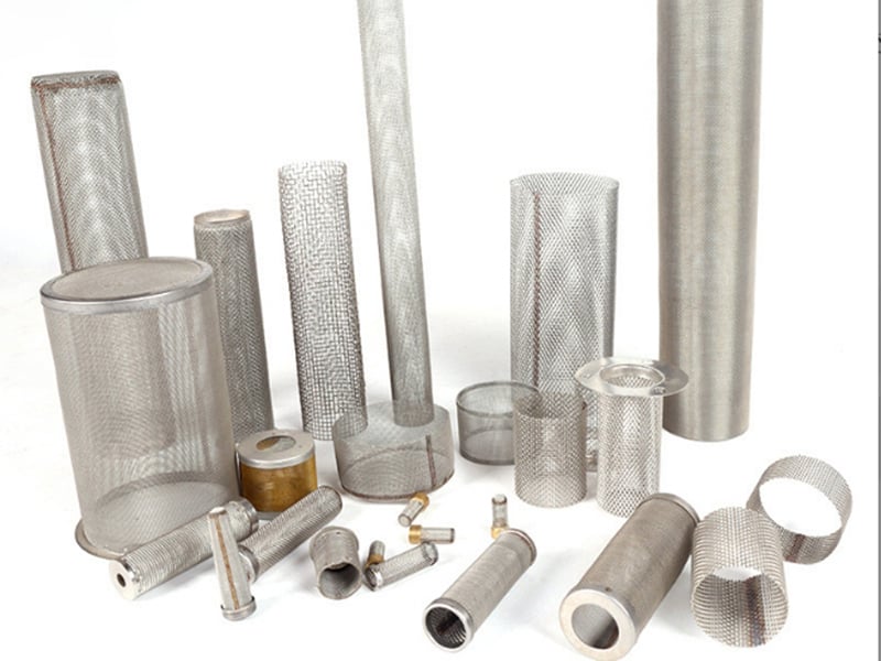
These real Maidong products show basket bodies, liners, handles, supported mesh and formed screens. They do not represent universal machine fit, capacity, pressure drop or coolant compatibility.
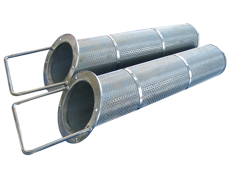
Removable perforated and mesh-lined baskets combine chip collection, drainage and service access.
Mesh-lined handled baskets
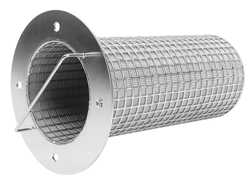
The flange, seating boundary, liner and handle must follow the machine or coolant-tank interface.
Flanged basket insert
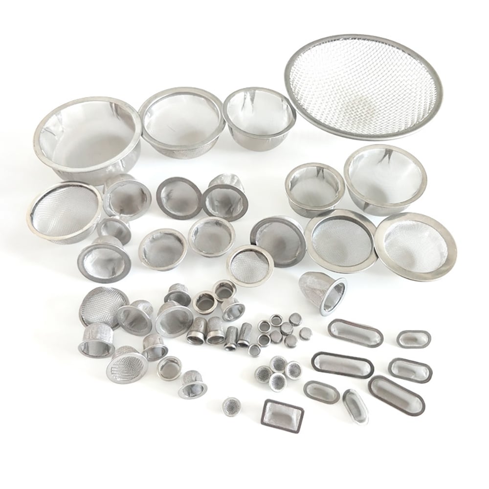
Coolant filtration components may be formed as baskets, cups, cylinders or framed screens to a drawing.
Custom coolant-filter forms
Formed screens illustrate drawing-defined depth, rim and mesh construction for equipment-specific filtration.
Formed screens and cups
Five-Step Coolant Filter Basket RFQ
1. Send the machine interface
Provide opening, seat, depth, clearance and removal path.
2. Describe chips and coolant
State material, shape, size range, loading and coolant condition.
3. Define filtration
Add hole or mesh opening, liner, support and active area.
4. Add hydraulic duty
Flow direction/rate, head or differential pressure and level limits.
5. Complete the RFQ
Include handle, drainage, cleaning, acceptance, quantity and revision.
It is a removable metal basket or insert installed at a sump, tank return, pump inlet or equipment opening to collect chips and specified particles from recirculating machining coolant.
Provide the installation drawing, basket envelope and seat, chip type and loading, coolant, opening or liner, flow, pressure or liquid head, handle and removal space, drainage, cleaning method and quantity.
Perforated metal can retain coarse chips or support a finer liner. Woven mesh can provide a smaller defined opening. The combination should follow the chip geometry, flow area, cleaning and structural duty.
Define the particle or chip dimensions that must be stopped and the downstream equipment being protected. Long, flat or curled chips behave differently from near-spherical particles, so mesh count alone is not enough.
Show the seating face, rim or flange, clearances, seal if present, and every path around the liner or frame. Correct mesh cannot prevent bypass through an incomplete interface.
Many metal baskets are selected for cleanability, but the safe method and practical reuse depend on chip load, coolant, media, joints, support, damage limits and the agreed acceptance criteria.
Request a Coolant Filter Basket Review
Send the machine or tank interface, chip and coolant details, filtration structure, flow conditions, handle and drainage requirements, drawing and quantity.