
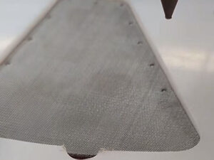
Perforated Metal Ventilation Panels for Industrial Equipment

INDUSTRIAL AIRFLOW AND EQUIPMENT PANELS

Perforated Ventilation Panels Built From the System Drawing

A perforated metal ventilation panel should be specified by material, thickness, hole geometry, pitch, open area, perforated zone, blank margins and finished equipment interface. Open area is important, but it does not by itself guarantee fan airflow or system pressure drop.

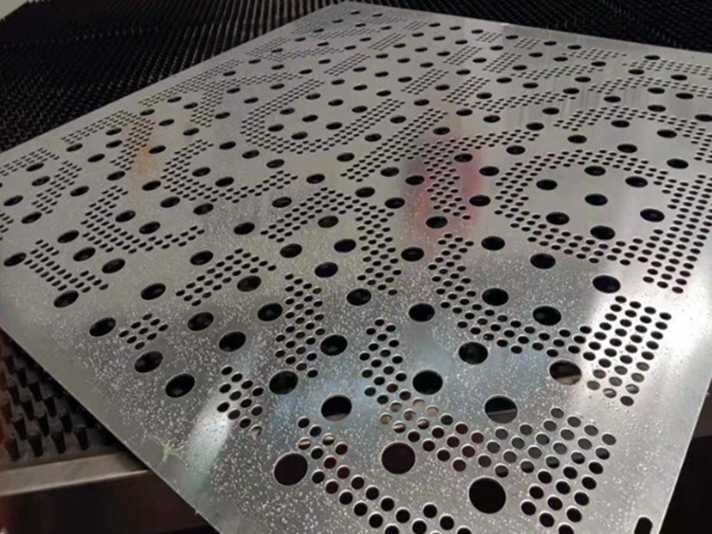
Custom perforated metal panel with mixed round hole pattern
Custom hole zones and blank margins should be defined on the panel drawing.

Six Decisions Define a Ventilation Panel

Hole geometry

Round, slotted, square, hexagonal or custom pattern.

Pitch and layout

Straight, staggered or drawing-defined orientation.

Material and thickness

Specified from environment, stiffness and forming needs.

Open area

Calculated from hole size, pitch and pattern.

Panel geometry

Perforated zone, blank margins, cut-outs, bends and holes.

Equipment interface

Frame, flange, fasteners, clearances and tolerances.

Perforated Ventilation Panel Specification Table

Drawing fieldWhat to stateWhy it matters
OpeningHole/slot shape and dimensionsDefines passage geometry
Pitch and patternCentre spacing, stagger and orientationControls ligaments and open area
Material/thicknessRequired grade and sheet thicknessAffects stiffness, forming and environment review
Perforated zonePattern boundaries and blank marginsProtects mounting and bend areas
Finished panelLength, width, cut-outs, bends, frame and tolerancesDetermines equipment fit
Performance inputOpen-area target or system airflow/pressure-drop requirementSeparates geometry from system validation
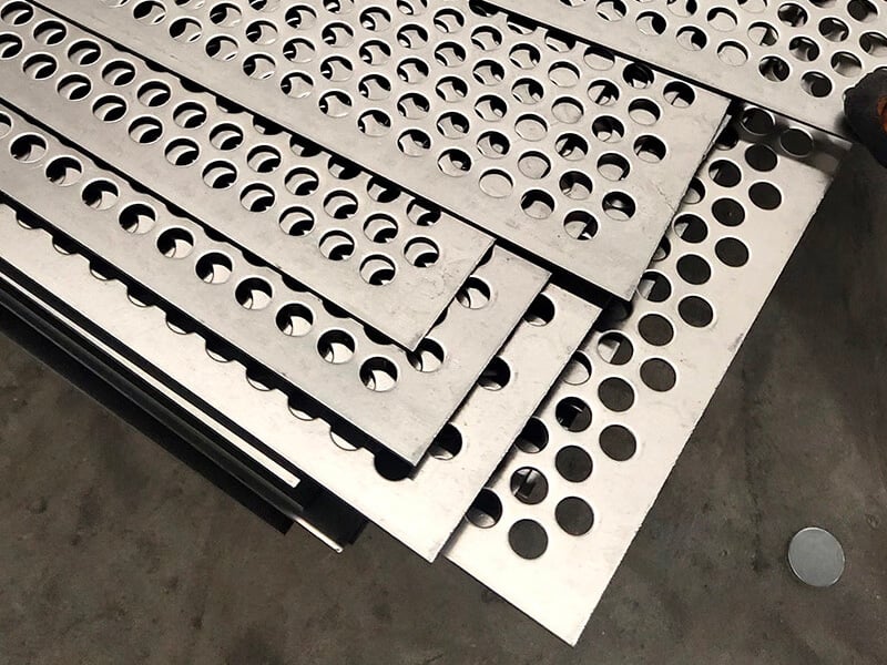
Stacked round hole perforated metal panels
Hole diameter, pitch, pattern, material thickness and edge margins define the panel.

Round-Hole Panels

Round holes can be arranged in straight or staggered layouts. Specify hole diameter, transverse and longitudinal pitch, layout angle, sheet thickness and unperforated margins. Do not assume that two panels with the same hole diameter have the same open area.

See round-hole perforated metal for product details.

Slotted Panels and Directional Layouts

Slots require length, width, end shape, centre spacing and orientation. Their directional layout can suit elongated airflow paths, drainage or equipment geometry, but the final system response must be evaluated in context.

Compare slotted-hole perforated metal.

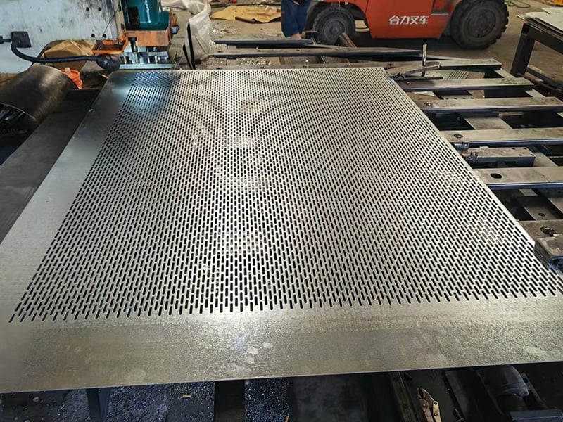
Large slotted perforated metal sheet on a fabrication table
Slotted ventilation panels require slot length, width, pitch, orientation and margins.
Close view of hexagonal perforated metal panel
Hexagonal openings offer a different ligament and open-area geometry from round holes.

Square and Hexagonal Opening Options

Square and hexagonal openings create different ligament networks and area relationships from round holes. Specify corner geometry, orientation, pitch, material thickness and permitted edge condition instead of selecting from appearance alone.

Review square-hole and hexagonal-hole perforated metal.

Open Area Is Not the Same as System Airflow

Panel open area

A geometric percentage calculated from the perforation pattern.

Free-flow path

The effective passage after frames, guards, louvers or filters.

Pressure loss

Depends on geometry, thickness, velocity and surrounding system.

Fan operating point

Must be checked using the complete equipment airflow system.

Use the perforated metal open-area calculator for geometric checks. It does not replace system pressure-drop testing or fan selection.

Blank Margins, Bends and Mounting Details

Keep critical bends, frames and fastener locations inside controlled blank zones where required. Show bend lines, radii, hole-to-edge distance, mounting holes, cut-outs and datum references on the finished panel drawing. A pattern that works on a flat sheet may need adjustment near a formed edge.

The main perforated metal mesh page covers the broader material family.

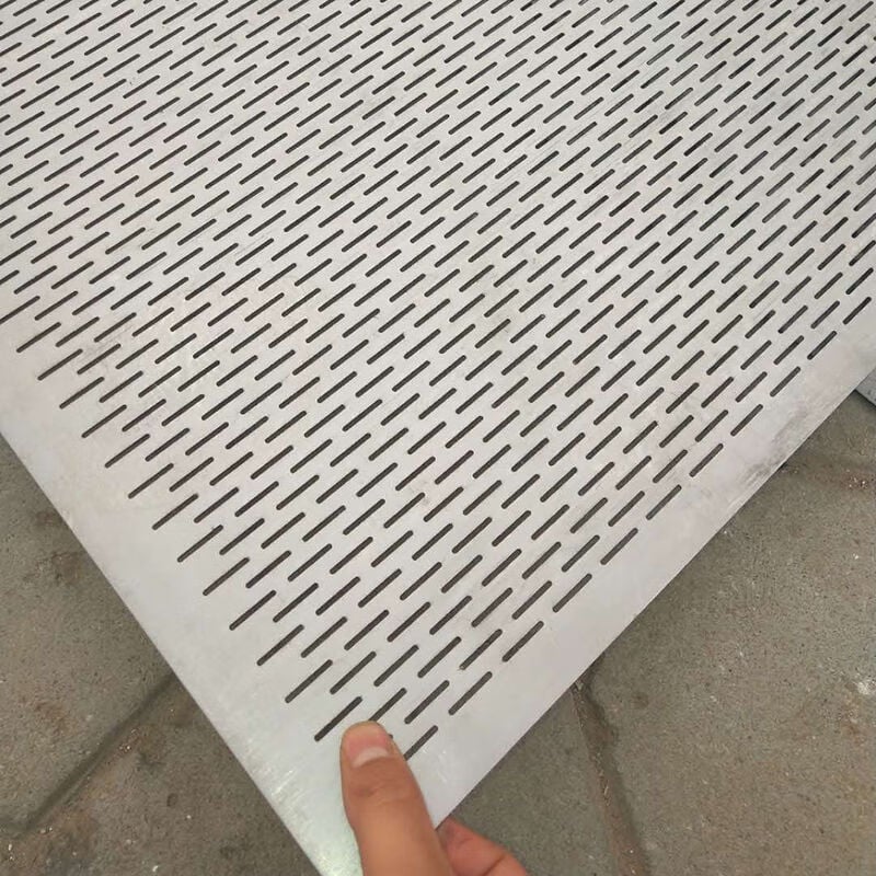
Fine slotted perforated metal ventilation panel detail
Fine slots can be oriented to suit the drawing, but airflow must be evaluated from the complete system.

Industrial Ventilation Panel Uses

Equipment enclosures

Air passage and component guarding around cabinets or machinery.

Fan and intake guards

Perforated screens with drawing-defined clearance and mounting.

Heat-management panels

Airflow openings incorporated into housings and protective covers.

Application labels do not establish airflow, strength, safety or acoustic performance. Those requirements must be stated and validated for the actual equipment.

Real Perforated Panel Examples

These Maidong material-library images show different hole patterns and manufacturing formats. They illustrate available design directions only; final specifications are confirmed from the approved drawing.

Custom perforated metal panel with mixed round hole pattern
Custom hole zones and blank margins should be defined on the panel drawing.

Custom mixed pattern

Stacked round hole perforated metal panels
Hole diameter, pitch, pattern, material thickness and edge margins define the panel.

Round-hole panels

Large slotted perforated metal sheet on a fabrication table
Slotted ventilation panels require slot length, width, pitch, orientation and margins.

Slotted sheet

Ventilation Panel RFQ Checklist

1. Define the opening

State hole/slot dimensions, pitch, layout and orientation.

2. Define the sheet

Add material, thickness and surface requirements.

3. Mark the pattern zone

Show blank margins, cut-outs and edge conditions.

4. Complete the panel

Add bends, frame, mounting, tolerances and drawing revision.

5. Add performance data

State open area or system airflow requirements and quantity.

Perforated Metal Ventilation Panel FAQ

State material, thickness, hole or slot size, pitch, pattern, open-area target, perforated zone, blank margins, finished dimensions, tolerances, forming, surface requirement and quantity.

Not automatically. Panel open area is one resistance input, but system airflow also depends on hole geometry, panel thickness, inlet conditions, guards, filters, fans and downstream restrictions.

Round holes are common, while slots, squares and hexagons can suit different area, drainage, direction or design requirements. The choice should follow the equipment drawing and performance target.

Pitch is the centre-to-centre spacing of adjacent openings. Open area is the percentage of panel surface removed by the pattern. The same hole size can produce different open area when pitch or layout changes.

A panel can be reviewed for bends, flanges, frames, mounting holes and cut-outs when these are shown on the drawing. Material, thickness, perforation zone and bend location affect manufacturability.

Provide the panel drawing, material, thickness, hole pattern, pitch, open area or airflow requirement, margins, dimensions, bends, mounting details, surface requirement, quantity and acceptance criteria.

Send the Panel Drawing and Airflow Requirement

Include hole pattern, pitch, material, thickness, perforated zone, margins, finished dimensions, bends, mounting details, tolerances, quantity and any system performance requirement.

Need help choosing the right mesh?

Related Articles