INDUSTRIAL GAS · CYLINDRICAL REPLACEMENT ELEMENT

Industrial Gas Sintered Wire Mesh Filter Cartridge

An industrial gas sintered wire mesh filter cartridge is a drawing-specific cylindrical porous element. Select it from the complete gas composition, particles or aerosols, flow basis, temperature, pressure, clean and loaded differential pressure, rating definition, layer structure, support, end connection, sealing and cleaning method.

Custom cylindrical sintered wire mesh filter cartridges for industrial gas housings
Drawing-specific sintered mesh cartridges illustrating possible body lengths and end interfaces.

Define the Industrial Gas Duty Before Selecting the Cartridge

Gas composition

List every gas constituent, moisture, condensables, impurities and safety classification.

Particles or aerosols

Describe solid or liquid contaminant, size distribution, loading and acceptable passage.

Flow basis

State mass flow or volumetric flow and whether volume is normal, standard or actual.

Operating envelope

Give temperature, absolute or gauge pressure, clean drop, loaded and reverse differential pressure.

Industrial Gas Sintered Cartridge RFQ Matrix

The words air or gas and one micron value do not define a filter cartridge. Record the operating state and the finished-element interface on the same specification.

RFQ fieldWhat to provideWhy it changes selection
Gas and stateComposition, moisture/condensables, safety, temperature and absolute/gauge pressureGuides material, joints, seals and volumetric conditions
ContaminantSolid or aerosol, size distribution, shape, loading and acceptable passageDefines retention basis and loading duty
Flow basisMass flow or normal/standard/actual volumetric flow with reference conditionsRequired for comparable face velocity and clean pressure drop
Pressure dutyClean loss, normal, terminal, maximum and reverse differential pressureControls area, support, seam and layer orientation
CartridgeOD, ID, length, layers, support, ends, seals, tolerances and flow directionControls fit, bypass boundary and mechanical loading
Cleaning and acceptanceMethod, fluid/gas, temperature, direction, pressure and post-cleaning checksLinks reusable intent to the complete assembly
Sintered wire mesh filter cartridge body and interface details
Real Maidong filter-element details for geometry discussion, not a universal performance claim.

Sintered Wire Mesh Layer Structure

Sintering bonds selected woven layers into a stable porous laminate. A fine retention layer may be combined with protection, distribution and structural support layers. Record the complete layer sequence, flow direction, porous thickness and any downstream or upstream support.

Compare the retention and flow questions with the permeability vs micron-rating guide and the powder vs sintered wire mesh comparison.

Flow, Clean Pressure Drop and Structural Differential Pressure

Reference condition

For gas volume, state whether the value is normal, standard or actual and give its reference temperature and pressure. Use the actual vs standard gas-flow guide to prepare comparable inputs.

Clean resistance

State the clean cartridge pressure drop at the named gas condition and flow.

Loaded condition

Define normal and terminal differential pressure and the process endpoint.

Reverse duty

State any blowback, backflow or upset load, duration and support direction.

Line pressure, clean pressure drop and differential pressure are different inputs. Use the metal-filter differential-pressure RFQ guide when preparing comparable values.

Cartridge Body, Ends and Bypass Boundary

The porous body cannot be separated from its end interfaces. Define OD, ID, length, wall build, active area, seam, support side, closed or open end, thread or flange standard, sealing face, gasket or O-ring location, installation clearance and critical tolerances.

The broad industrial gas filtration wire mesh page explains media and element-family selection. The custom sintered filter cartridge page covers cross-industry cartridge construction.

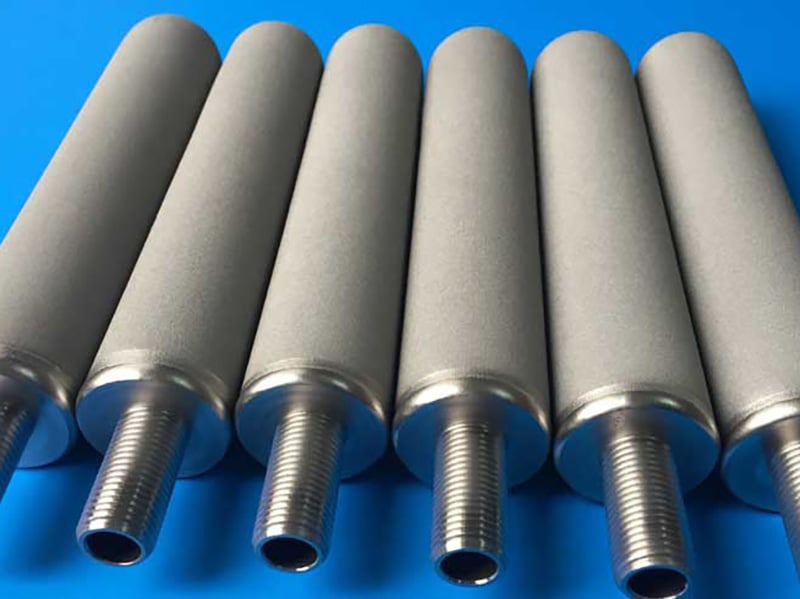
Threaded cylindrical sintered mesh gas filter elements
Threaded porous elements whose connection and sealing details must match the housing drawing.

Industrial Gas Cartridge Configuration Options

Open-end tube

Requires the housing to define closure, seal, retained side and removal method.

Threaded element

Needs thread standard, engagement, sealing method and installation torque boundary.

Welded end assembly

Needs alloy, joint location, cleanliness and drawing-defined inspection requirements.

Supported porous wall

Support location follows flow direction and normal, loaded or reverse differential pressure.

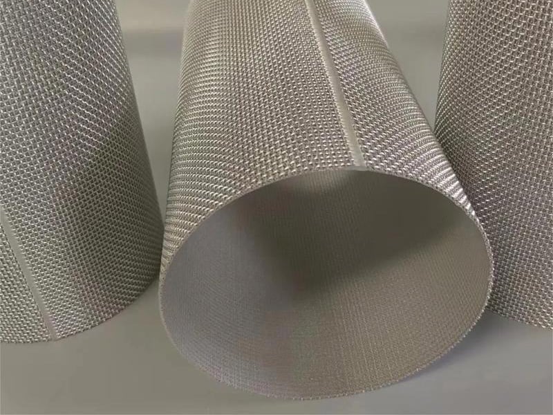
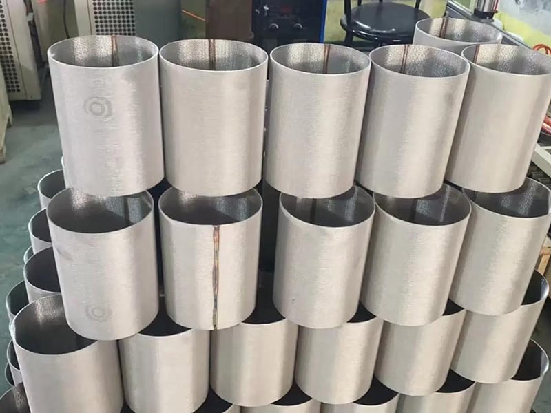
Open cylindrical sintered wire mesh filter tubes for gas filtration assemblies
Open porous tubes before drawing-defined ends, supports and seals are added.
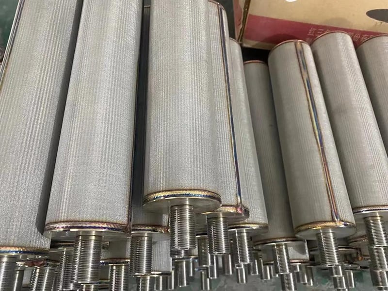
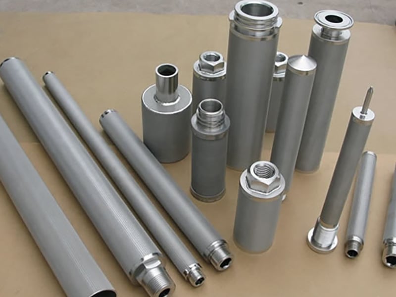
Stainless steel sintered mesh cartridges with different end connections
Different end formats illustrate why interface dimensions must be controlled by an approved drawing.

Real Maidong Sintered Mesh Cartridge Examples

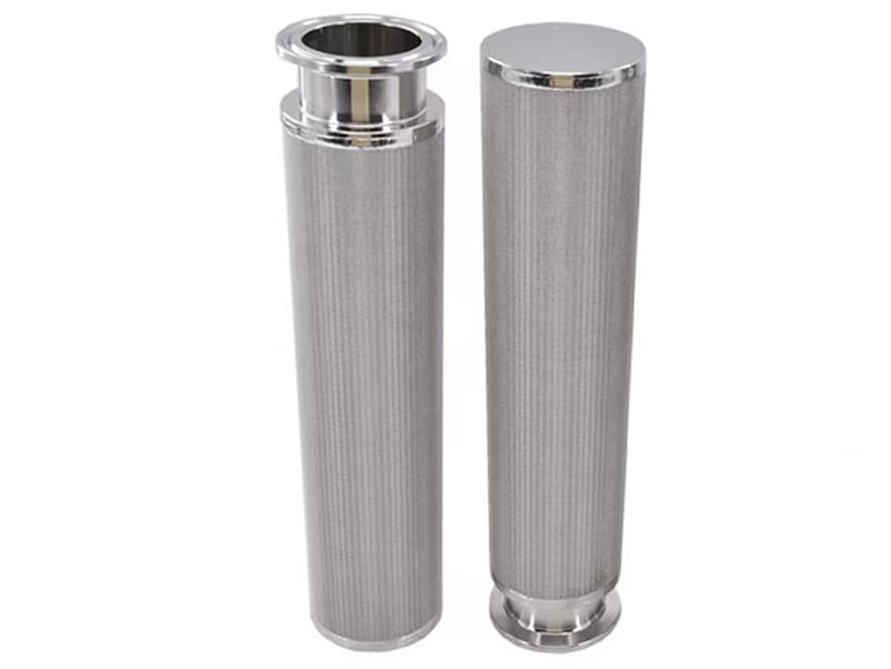
These real product images show cylindrical porous bodies and possible end formats. They do not establish gas compatibility, filtration efficiency, pressure capacity, hazardous-service suitability or service life without a complete specification.

Custom cylindrical sintered wire mesh filter cartridges for industrial gas housings
Drawing-specific sintered mesh cartridges illustrating possible body lengths and end interfaces.

Cylindrical cartridge formats

Threaded cylindrical sintered mesh gas filter elements
Threaded porous elements whose connection and sealing details must match the housing drawing.

Threaded interfaces

Custom sintered mesh cylindrical cartridge bodies for industrial gas filtration
Cylindrical porous bodies showing possible diameters, lengths and support arrangements.

Body lengths and supports

Sintered wire mesh filter cartridge body and interface details
Real Maidong filter-element details for geometry discussion, not a universal performance claim.

Porous body details

Service and Safety Boundaries

Mechanical filtration

Specify the required particle-removal performance and its test basis. If the duty includes liquid aerosols, request application-specific validation; a sintered mesh or micron designation alone does not establish coalescing, oil-removal or mist-removal performance.

Not molecular separation

It does not by itself remove dissolved gases, odours, vapours or molecular contaminants.

Condensation matters

Moisture and condensables can change phase, loading, drainage and pressure-drop behavior.

Special gas service

Flammable, oxygen, toxic, high-purity or regulated duty requires buyer-defined safety and cleanliness requirements.

Five-Step Industrial Gas Cartridge RFQ

1. Define gas

Composition, moisture/condensables, safety, temperature and pressure.

2. Define contaminant

Particles or aerosols, size, loading, passage and rating basis.

3. Define flow

Mass or reference-condition volume, clean drop and loaded cycle.

4. Define cartridge

Specify layers, dimensions, support, flow direction, ends, seals and tolerances. Attach a dimensioned cartridge drawing with controlled tolerances.

5. Define acceptance

Cleaning, integrity, dimensional checks, drawing revision and quantity.

Industrial Gas Sintered Wire Mesh Cartridge FAQ

It is a cylindrical replacement element made from bonded woven-wire layers and drawing-defined ends, supports and seals. It is used for mechanical retention of defined particles or aerosols in a specified gas duty; it does not remove molecular contaminants by itself.

State the complete gas composition, moisture or condensable content, safety classification, operating and design temperature and pressure, and whether the flow value is based on normal, standard or actual conditions.

Provide contaminant type, size distribution, shape, loading and acceptable downstream passage, together with a geometric, nominal, absolute or named test basis. A micron number alone is incomplete.

Clean pressure drop describes flow resistance at a stated gas condition and flow. Differential pressure describes structural loading during normal, loaded, upset or reverse-flow conditions. Both are required.

Only when the media layers, flow direction, support, seams, ends, seals and housing are designed for the named cleaning method. State the cleaning fluid or gas, pressure, temperature, direction and acceptance criteria.

Send gas and contaminant data, flow basis, temperature, pressure, clean and terminal differential pressure, rating definition, media layers, OD, ID, length, support, flow direction, end connection, seal, cleaning method, drawing revision and quantity.
Request an Industrial Gas Cartridge Review

Send the gas and contaminant data, flow reference conditions, temperature, pressure-drop and differential-pressure duty, cartridge drawing, layer and support requirements, end connection, seal, cleaning method, acceptance and quantity.