Filter Element Effective Filtration Area Calculator & Guide
Effective filtration area is the portion of filter media exposed to process flow after excluding solid ends, rims, seams, overlaps, support contact and other blocked regions. Calculate the geometry first, then evaluate media permeability, flow, viscosity and differential pressure separately.
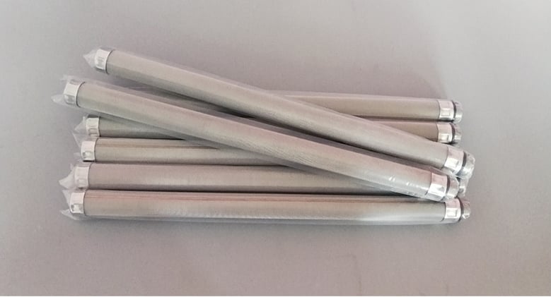
Cylindrical elements illustrating the diameter and active-length inputs used for exposed-area calculations.
Direct Answer: Do Not Use Envelope Area as Active Area
Geometric area
Projected disc face or exposed cylindrical surface before deductions.
Exposed media area
Geometric area after solid edges, ends, seams and blocked zones are removed.
Media flow structure
Open area, pore path or permeability belonging to the actual filtration medium.
Operating duty
Flow, viscosity, temperature and differential pressure used to evaluate the element.
Filter Element Effective Area Calculator
Select a straight cylindrical active surface or flat annular disc. Use controlled active dimensions—not the overall component envelope. The optional deduction is for a known blocked-area estimate from the drawing.
Enter the controlled active dimensions.
This calculator estimates exposed geometric area only. It does not calculate pressure drop, retention efficiency, permeability, dirt capacity or a guaranteed operating limit.
Area Formulas and Drawing Boundaries
Element form
Starting formula
Do not include
Drawing check
Straight cylinder
A = π × D × L
Solid caps, fittings and nonporous bands
Use active media diameter and exposed length
Flat annular disc
A = π/4 × (OD² − ID²)
Solid rim, center hub and clamped edge
Count one projected face, not both sides
Porous closed end
Add πD²/4 when exposed
Welded cap or end blocked by hardware
Confirm the end shares the same flow duty
Pleated media
Use controlled developed-media area
Bonded ends and inaccessible folds
Envelope dimensions alone are insufficient
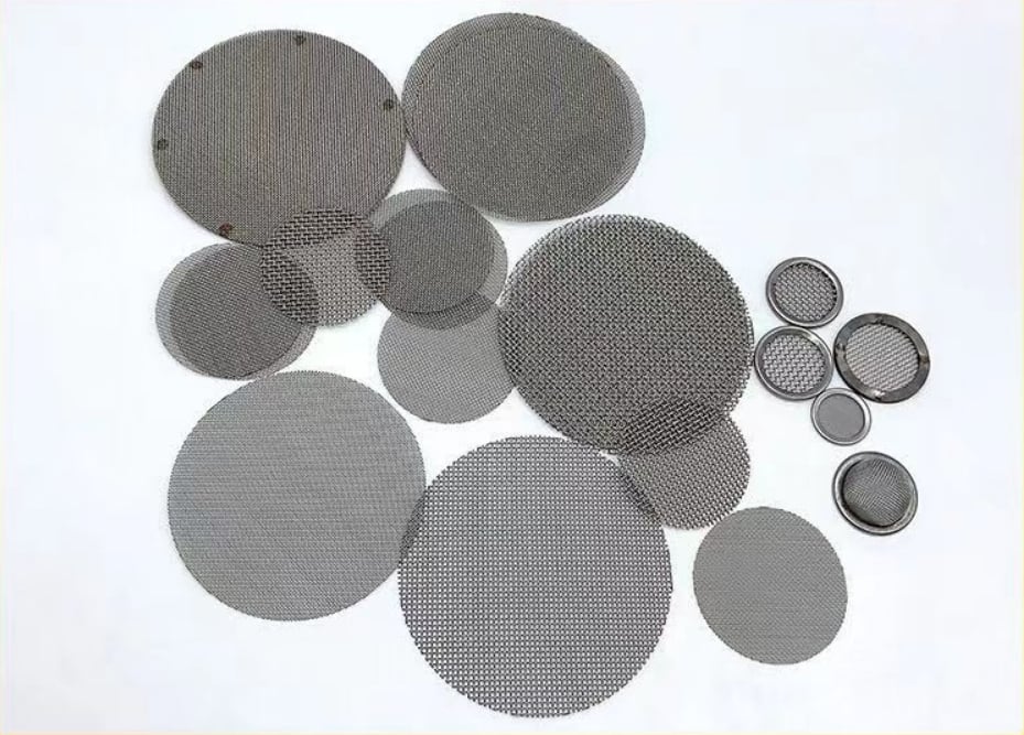
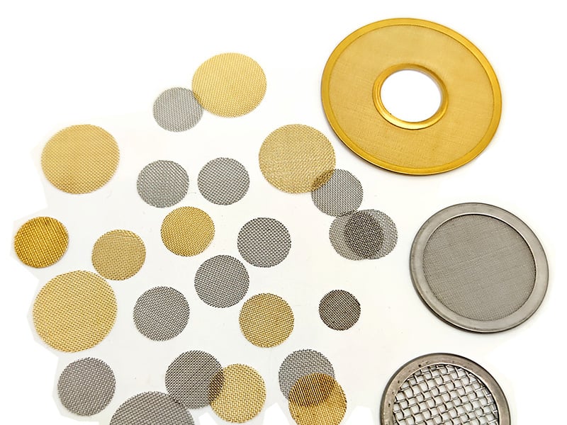
Round discs showing that outside diameter alone does not identify the usable filtration face.
Filter Disc Area: Count the Flow Face Once
A flat disc normally receives flow through one projected annular face. Counting the front and back as two independent areas doubles the same through-thickness flow path. Subtract the solid rim, center hole or hub, clamped band and any blocked frame area.
For a straight cylindrical filtering wall, use π × active diameter × exposed active length. Add a porous end only when it is open to the same filtration duty. Exclude threaded fittings, welded collars, seal bands and nonporous transitions.
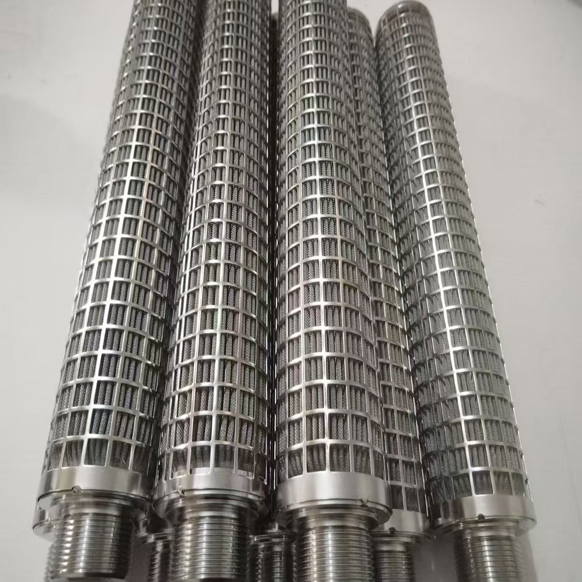
End fittings, support contact and nonporous zones can reduce the exposed media area.
What Reduces the Usable Exposed Area?
Solid edges and end fittings
Rims, caps, collars, threaded ends and seal bands are not porous flow area.
Seams and overlaps
Longitudinal overlaps, welded bands and bonded regions can block part of the media.
Support contact
Perforated, expanded or grid supports have solid contact and margin regions.
Housing shadow
Seats, clamps, breaker plates and internal hardware may cover otherwise porous media.
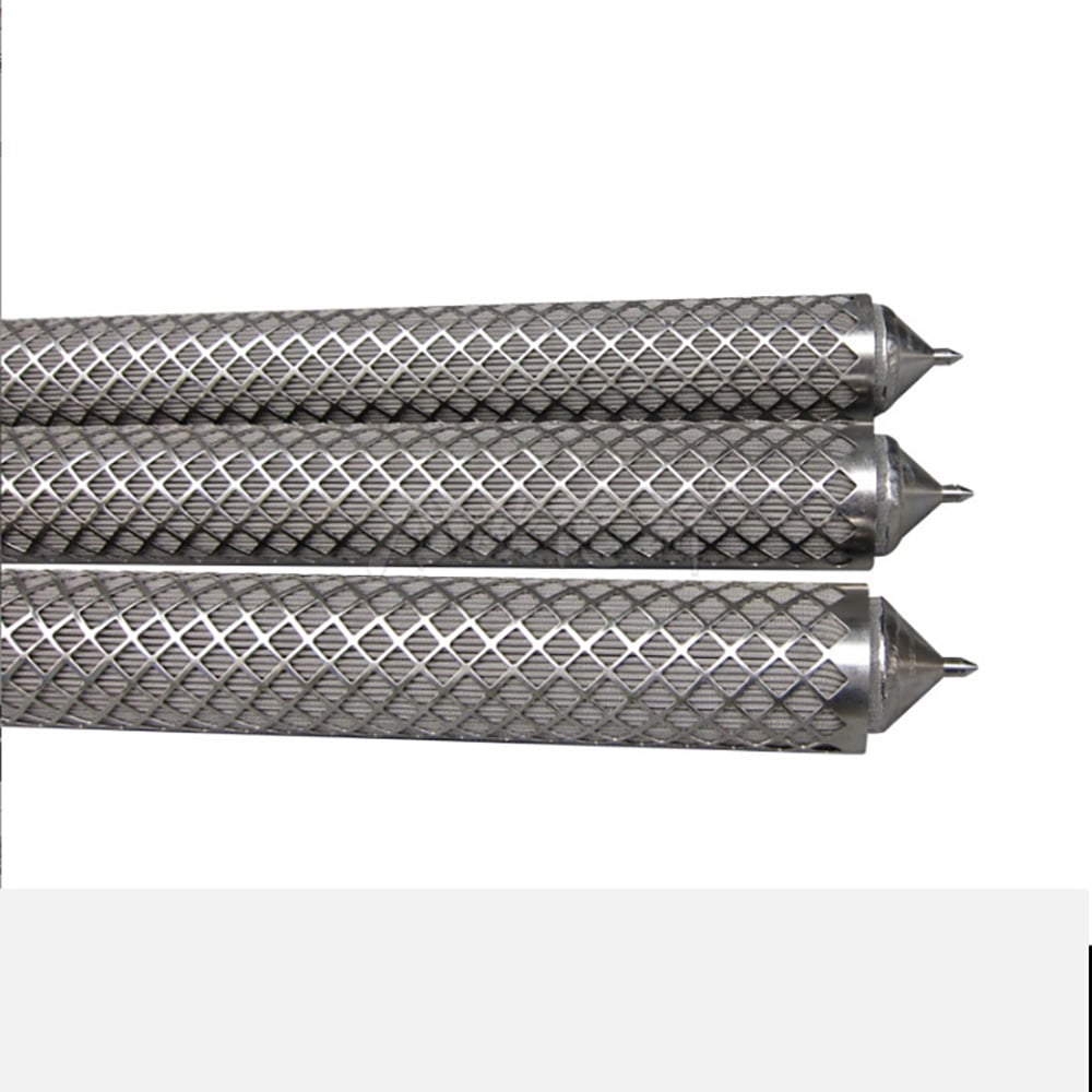
An open support structure may still create contact and blocked regions that should be reviewed separately.
Fine filtration media, support layers and finished edges perform different functions in an area calculation.
Why Equal Area Does Not Mean Equal Pressure Drop
Two elements with the same exposed geometry can have different hydraulic behavior because the filtration medium, wire diameter, weave, pore path, layer stack, support contact, fluid viscosity and contaminant loading differ. Do not convert exposed area directly into a flow guarantee.
It is the portion of the filtration medium actually exposed to process flow after excluding solid rims, end fittings, seams, overlaps, blocked support contact and other non-flow regions. Geometric exposed area is a starting value, not a complete hydraulic performance rating.
For a straight cylindrical active surface, use A = pi × D × L, where D is the active media diameter and L is the exposed active length. Add a porous end only when that end is exposed to the same filtration duty.
No. For normal through-thickness flow, the projected annular face is counted once. Counting both faces doubles the same flow path rather than creating twice the independent inlet area.
No. Filter-element area describes exposed geometry. Media open area or permeability describes the flow paths within the woven or porous structure. They must be specified separately.
Use the developed area of the actual pleated media pack, excluding bonded ends and blocked regions. Envelope diameter and length alone are not enough; obtain the controlled pleat geometry or verified developed-media area.
Provide the geometry and active dimensions, media construction, blocked regions, layer and support arrangement, flow direction, fluid and viscosity, flow rate, clean and loaded differential pressure, cleaning method and drawing revision.
Request an Area and Filter Drawing Review
Send the active dimensions, blocked regions, media and support construction, flow direction, operating duty and complete filter drawing. Maidong can review the information needed for a custom filter RFQ.