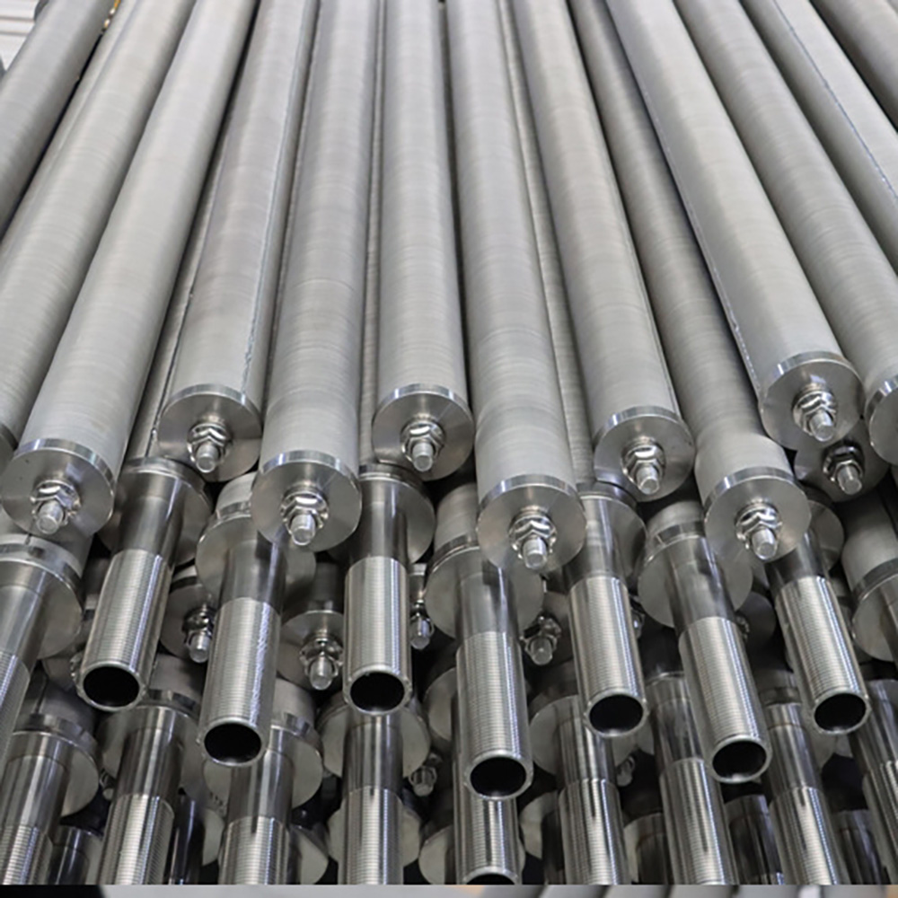
A metal filter element integrity test must define what boundary is being checked, which method is used, the test conditions and the pass/fail rule. Bubble point, pressure decay, flow testing, dimensional inspection and joint examination answer different questions and should not be treated as interchangeable.
Integrity review covers the porous body, seams, end joints and equipment-facing interfaces.
Direct Answer: Start with the Question the Test Must Answer
Fabrication integrity
Is there an unintended opening, discontinuity or local leak path?
Porous-media behavior
At what defined condition does gas first pass through a wetted pore path?
Assembly leakage
Does the sealed test boundary lose pressure or pass gas beyond an agreed limit?
Fit and acceptance
Do the finished dimensions, joints and interfaces meet the released drawing?
Filter Element Integrity Test Selection Matrix
Choose a check from the failure mode and acceptance question. Combining several methods may be necessary when the media, seals and structural joints perform different functions.
Check
Primary question
Must be defined
Does not prove by itself
Visual and dimensional inspection
Does the finished part match drawing features?
Datums, dimensions, tolerances, surface and sampling
Pore integrity or filtration efficiency
Bubble-point / fabrication-integrity method
Where and when does gas first pass a wetted path?
Method, wetting fluid, fixture, pressure ramp and observation
Universal micron rating, efficiency or dirt capacity
Pressure decay or gross-leak check
Does a sealed boundary lose pressure beyond a limit?
Volume, pressure, time, temperature, fixture leakage and limit
Largest pore or retention performance
Flow / pressure-drop comparison
Is hydraulic resistance consistent at stated conditions?
Fluid, temperature, flow, clean condition and fixture
Absence of every local bypass path
Joint-specific examination
Does a seam, end joint or closure meet its function?
Joint function, examination method, location and acceptance
Whole-element performance outside that boundary
A threaded adapter, porous body and closed end create separate inspection boundaries.
Bubble Point: What It Can and Cannot Tell You
In a wetted porous element, gas pressure must displace liquid from a pore path before a sustained bubble is observed. The result changes with the wetting liquid, surface interaction, temperature, geometry, fixture and the definition of the first observable bubble.
ISO 2942:2018 describes fabrication-integrity and first-bubble-point testing for hydraulic filter elements. ISO explicitly notes that first bubble point is not a functional filtration characteristic and cannot be used by itself to estimate rating, efficiency or retention capacity.
Identity, condition, compatibility and complete wetting procedure.
Temperature
Liquid and element condition because fluid properties influence the result.
Fixture and boundary
Sealed areas, immersed or observed surface, adapters and fixture-leak control.
Pressure sequence
Ramp rate, stabilization, observation point and maximum allowed exposure.
Bubble definition
First isolated bubble, continuous stream or another stated observation rule.
Element orientation
Position and gas path during the test, especially for complex geometries.
Acceptance limit
Named standard, drawing value or approved sample-based criterion.
Report content
Element ID, procedure revision, conditions, result, location and disposition.
Test Boundary: Media Coupon vs Complete Filter Element
A media coupon can characterize a controlled porous sample. A complete-element test can include the body seam, media-to-end joint, closure and adapters, but only inside the sealed fixture boundary. State whether seals and removable gaskets are included.
Different end-joint geometries require a clearly defined test boundary and acceptance method.
Pressure Decay, Gross Leak and Flow Checks
Pressure decay
Define test volume, starting pressure, stabilization, duration, temperature and fixture background leakage.
Gas or liquid leak check
Define the test fluid, boundary, observation or measurement method and allowable limit.
Clean flow comparison
Compare only at the same fluid, temperature, flow, direction, fixture and clean condition.
Repeatability
Use a controlled procedure, calibrated equipment where required and a documented retest rule.
For hydraulic-resistance inputs, use the metal filter differential-pressure guide. A normal pressure-drop result does not independently prove that every seal or joint is leak-free.
Connection, shoulder and seal geometry should be inspected separately from the porous medium.
Dimensional, Seal and Joint Acceptance
Control installed length, connection diameter, seating face, thread or flange reference, concentricity and seal geometry on the finished element. Then identify which seams and end joints are part of the filtration boundary.
Real Maidong Filter Elements: Define the Boundary for Each Geometry
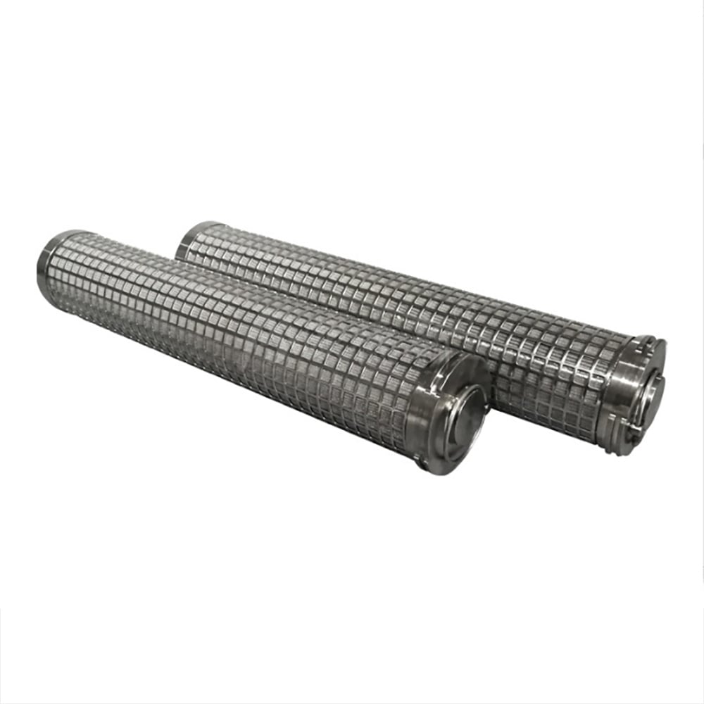
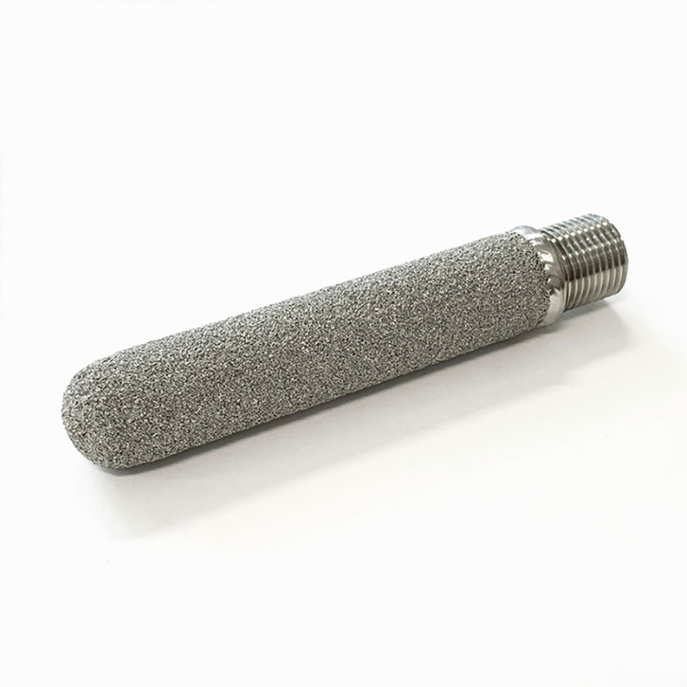
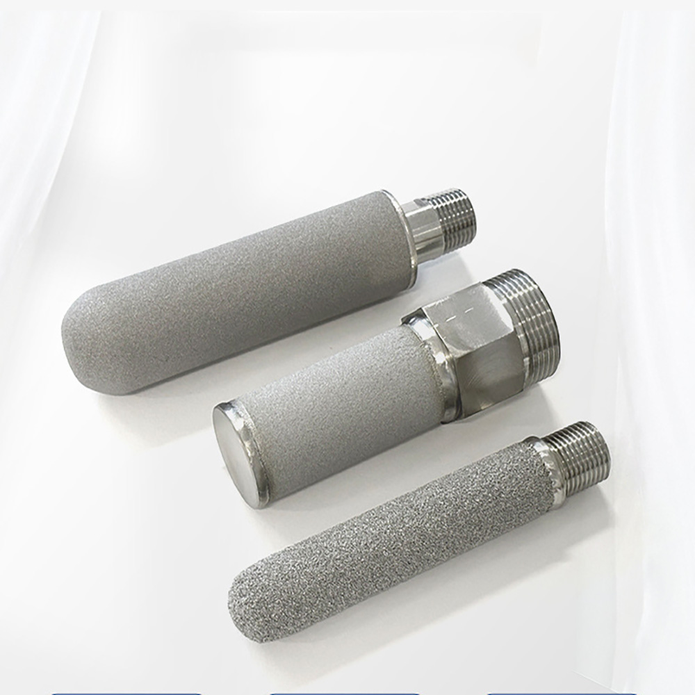
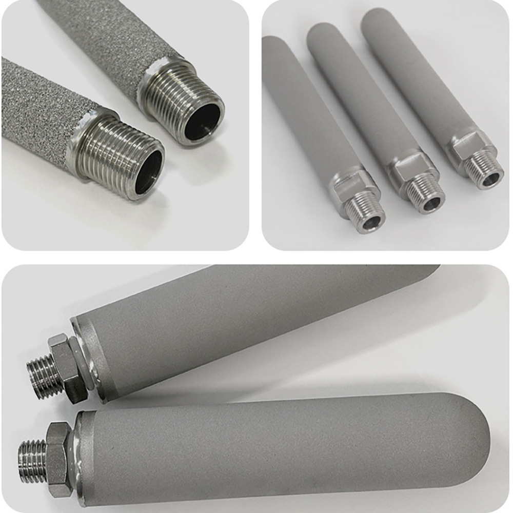
These genuine Maidong products show porous bodies, threaded adapters, closed ends, support structures and batch interfaces. They illustrate inspection locations, not claimed test results; acceptance limits must be defined for the actual project.
Integrity review covers the porous body, seams, end joints and equipment-facing interfaces.
Supported cylindrical assemblies
A threaded adapter, porous body and closed end create separate inspection boundaries.
Threaded porous element
Different end-joint geometries require a clearly defined test boundary and acceptance method.
Different end-joint geometries
Batch acceptance needs controlled dimensions, sampling and a documented pass or fail rule.
Batch interface consistency
Build an Unambiguous Integrity-Test Acceptance Plan
Do not place only “integrity tested” on the purchase order. Connect the test to the drawing revision, defined boundary, procedure and disposition rule.
Acceptance-plan field
Example of a controlled statement
Object and boundary
Complete element including named seams and end closures; removable housing seal excluded
Method
Named standard and edition, customer procedure or drawing-specific method
Conditions
Fluid, temperature, fixture, orientation, pressure sequence and stabilization
Sampling
Quantity or percentage, batch definition and sample selection rule
Pass/fail
Measured limit or observation rule plus location-specific requirements
Disposition
Retest rule, rejection handling, report content and traceability
Five-Step Filter Integrity Test RFQ
1. Define the failure mode
Pore discontinuity, seam leak, end-joint path, seal leak, fit or hydraulic inconsistency.
2. Mark the boundary
Identify the media, seams, closures, adapters, seals and fixture exclusions.
3. Select the method
Choose the check that answers the stated question and name the procedure.
4. Set the conditions
Control fluid, temperature, pressure sequence, orientation, fixture and sampling.
5. Define acceptance
State the pass/fail limit, report, traceability, retest and disposition rules.
It is an agreed check used to find unintended openings, discontinuities or bypass paths in a filter element or to verify a defined fabrication condition. The method and acceptance criterion must match the media, assembly and intended boundary.
No. First bubble point can help identify the largest liquid-filled pore or a fabrication discontinuity under a defined method, but it is not by itself filtration efficiency, retention capacity or a universal micron rating.
Not automatically. Pressure decay may reveal leakage from a defined sealed assembly, while a bubble-point method examines gas passage through a wetted porous path. The two methods answer different questions unless a validated procedure connects them.
State the boundary explicitly. A coupon can characterize media, while a complete-element check can include seams, end joints and closures. Neither result should be assumed to represent the other without an agreed correlation.
Record the test method, wetting liquid, liquid condition and temperature, fixture, immersed area or observation method, pressure ramp, stabilization, first-bubble definition, element orientation and acceptance criterion.
Identify the element drawing and revision, test boundary, named method or detailed procedure, test fluid, fixture, pressure sequence, sample quantity, acceptance limit, retest rule, report content and required traceability.
Request a Drawing and Acceptance Review
Send the filter drawing, media construction, test boundary, required method, conditions, sampling, acceptance limit, report requirements and quantity. Test capability and procedure must be confirmed for the actual project.