CUSTOM METAL FILTER · DRAWING & RFQ RESOURCE

Metal Filter Element Seam and Joining Guide

A metal filter joint can control geometry, retain fine media, transfer pressure load or prevent bypass. Specify every seam by its location, function, geometry, continuity, finished profile and acceptance requirement—not by writing only “welded.”

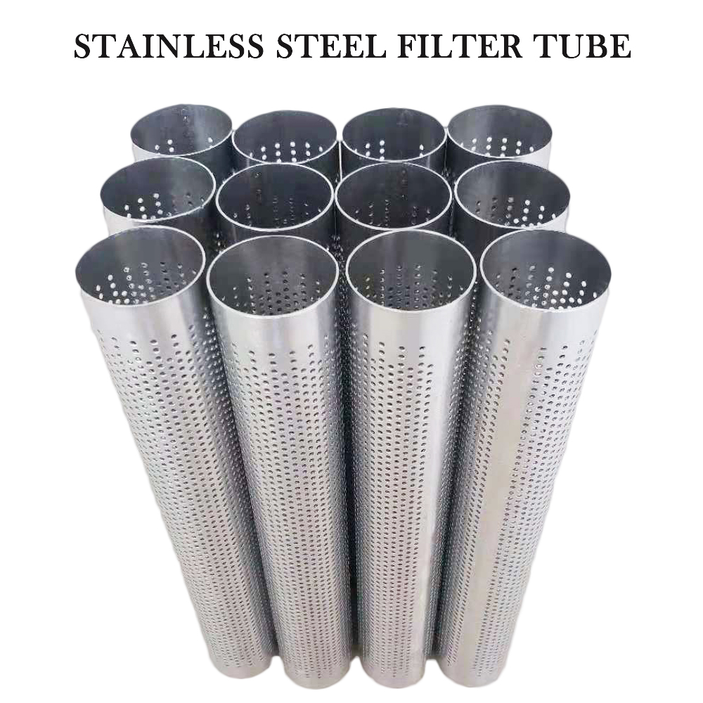
Perforated stainless steel filter tubes with visible longitudinal seams
Formed perforated tube bodies showing longitudinal seam locations.

Direct Answer: Define the Joint Function Before the Joining Process

Shape control

Forms flat mesh or sheet into a tube, cone, basket or framed component.

Media retention

Keeps the filtration layer in position without creating an unintended bypass path.

Load transfer

Connects media, support, rings, caps or fittings under stated pressure and handling loads.

Sealing boundary

Closes a path that must not allow fluid to pass around the filtration medium.

Metal Filter Seam and Joint Control Matrix

Use the function of each joint to decide what must be controlled. Not every attachment needs the same continuity, sealing or inspection requirement.

Joint locationDrawing controlsMain RFQ question
Longitudinal body seamButt/overlap geometry, position, width/profile, continuity and finished OD/IDDoes it control fit, load, bypass or all three?
Media-to-support jointLayer order, attachment zones, masked area and support directionCan the fine medium shift or lift under pressure?
End-cap or flange jointJoint location, penetration/attachment requirement, seal boundary and end dimensionsIs this joint part of the bypass boundary?
Support ring or frameSpacing, contact, attachment pattern and finished geometryWhat load or shape function does the support perform?
Layered disc edgeLayer sequence, edge treatment, frame/rim and filtration-area boundaryCan layers separate or fluid bypass the media?
AcceptanceVisual, dimensional, continuity, integrity or named test requirementHow will buyer and supplier judge the finished joint?
Perforated stainless steel filter tubes with visible longitudinal seams
Formed perforated tube bodies showing longitudinal seam locations.

Longitudinal Seams: Butt, Overlap and Finished Profile

A butt arrangement minimizes overlap thickness but requires edge alignment and a suitable joining route. An overlap arrangement can simplify edge retention but creates a local double-thickness area that may affect fit, open area and flow.

For the finished product context, review the custom welded filter tube. This guide owns the cross-product seam and RFQ intent.

Joining Process Families: Specify Requirements, Not Assumptions

Welded joint

Review material, thickness, heat input, distortion, active-area position and required continuity.

Brazed joint

Review filler compatibility, process cleanliness, joint clearance and service conditions.

Mechanical joint

Folded, crimped or locked forms require geometry, retention and bypass review.

Bonded multilayer media

Sintered laminates are selected as a complete porous construction, not a loose seam substitute.

These are selection categories, not a claim that every method is available for every part. The final manufacturing route and inspection scope require feasibility confirmation from the actual drawing.

Mesh Cylinder Seam Process Reference

Process reference: a cylindrical mesh workpiece moving beneath a wheel-shaped tool along its longitudinal seam. This silent excerpt illustrates a joining operation; it does not establish the material grade, process settings, seam integrity or acceptance results. Source: user-supplied video collection; factory ownership is unverified. It is not presented as Maidong factory footage.

Joining Fine Media to Structural Support

Fine woven mesh provides the retention function; perforated sheet, expanded metal or coarse mesh usually provides support. Define the layer order, high-pressure side, attachment region and maximum area that may be masked by the joint.

Use the flow-direction and support guide and metal filter differential-pressure guide when those pages are available to the reviewer.

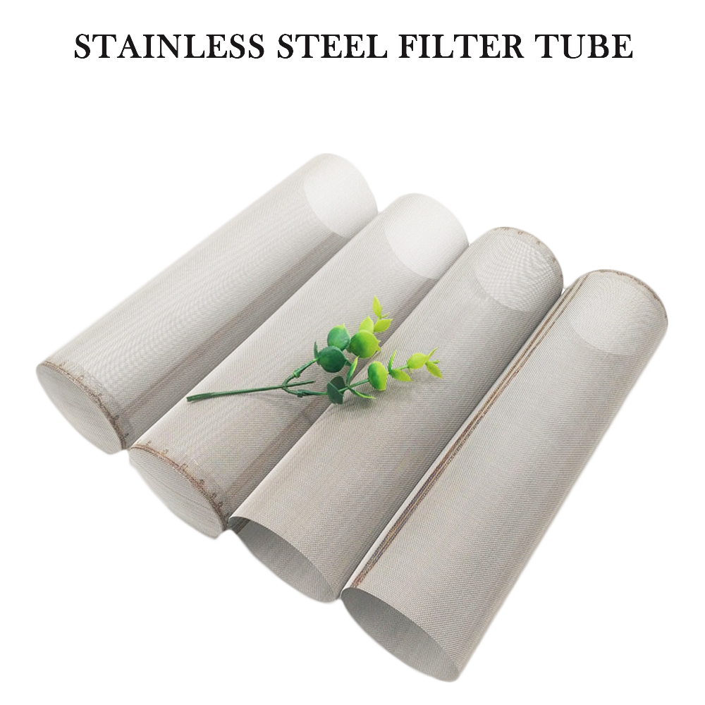
Stainless steel wire mesh cylinder bodies with formed longitudinal joints
Wire mesh cylinder bodies illustrating formed seams and end configurations.

End Caps, Flanges, Threads and Bypass Boundaries

End cap

Define attachment zone, closed/open function, pressure side and finished length.

Flange or collar

Control seating face, position, flatness, bolt pattern and filter-body attachment.

Threaded fitting

State thread, reference face, seal location, concentricity and joint to the filter body.

Media termination

Show how fine media ends and how fluid is prevented from passing around it.

Use the end connections and sealing guide for interface details.

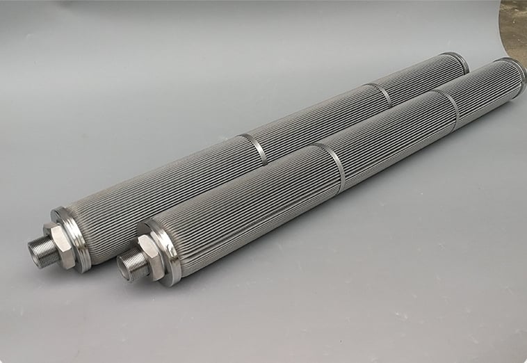
Filter elements with longitudinal bodies support rings and threaded end joints
Finished elements showing body seams, support rings and attached threaded ends.

Control Finished Dimensions After Joining

Forming and joining can change roundness, straightness, flatness, end-face position and seam profile. Put equipment-fitting dimensions and tolerances on the finished element drawing.

The filter element drawing and tolerance checklist helps separate critical dimensions from reference values.

Real Maidong Filter Joint Examples

These real products show body seams, support rings, end fittings and varied joined structures. They demonstrate where joints occur, not universal processes, strength values or acceptance standards.

Perforated stainless steel filter tubes with visible longitudinal seams
Formed perforated tube bodies showing longitudinal seam locations.

Longitudinal sheet seams

Stainless steel wire mesh cylinder bodies with formed longitudinal joints
Wire mesh cylinder bodies illustrating formed seams and end configurations.

Formed mesh cylinders

Filter elements with longitudinal bodies support rings and threaded end joints
Finished elements showing body seams, support rings and attached threaded ends.

Rings and threaded ends

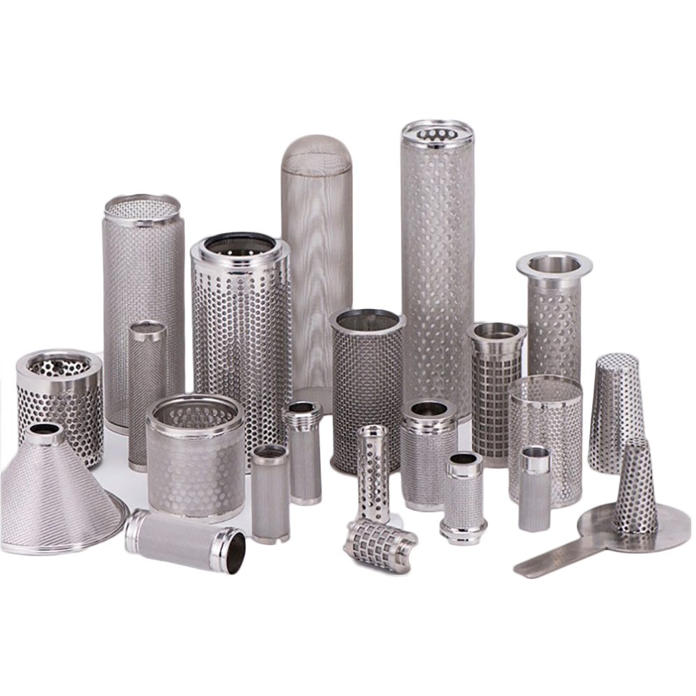
Custom metal filter tube configurations with varied seams bodies and ends
Different cylindrical and conical constructions require different joint definitions.

Custom joined geometries

Joint Acceptance: Match the Check to the Function

Visual condition

Profile, surface condition, incomplete attachment or damage where relevant.

Dimensional inspection

Finished OD/ID, length, flatness, roundness, seam height and interface position.

Continuity or integrity

Use only an agreed method and acceptance criterion tied to the joint function.

Media verification

Confirm opening/rating and ensure joining has not created an unintended bypass path.

Metal Filter Seam and Joining RFQ Checklist

1. Mark every joint

Show body seam, media/support, rings, edges, caps and fittings.

2. State each function

Shape, locate, carry load, retain media or prevent bypass.

3. Define geometry

Butt/overlap, profile, width, position and continuity.

4. Add service data

Media, flow, differential pressure, temperature and cleaning.

5. Define acceptance

Finished dimensions, inspection method, quantity and revision.

Metal Filter Seam and Joining FAQ

Identify seam location, joint function, butt or overlap geometry where relevant, width or profile, continuity, relationship to the active filtration area, permitted distortion and required inspection or acceptance condition.

No. Continuity depends on whether the joint must prevent bypass, retain media, carry load, locate layers or only hold parts during assembly. State the functional requirement instead of assuming every joint needs the same treatment.

A butt seam joins adjacent edges with little or no overlap, while an overlap seam places one edge over another. The choice affects local thickness, profile, effective opening, fit and joining access.

Define layer order, support side, attachment zones, allowed masked area, flow direction and differential-pressure loading. The fine medium should not be described only by the support-body specification.

Forming and joining can change roundness, straightness, flatness, end-face position or seam profile. Apply critical dimensions and tolerances to the finished component, not only the flat blank.

The process depends on materials, thickness, pore structure, joint function, contamination limits, thermal effects, geometry and inspection needs. Welding, brazing, mechanical locking or other methods require project-specific feasibility confirmation.
Request a Filter Joint Drawing Review

Send the media, support, joint locations and functions, finished dimensions, operating duty, acceptance requirements and quantity.