Metal Filter Element End Connections & Sealing Guide
A metal filter element end connection must locate the element, transfer mechanical load and control the intended sealing path. Specify the mating component, connection geometry, seal location, tolerances, flow direction and allowable bypass—not only “threaded” or “flanged.”
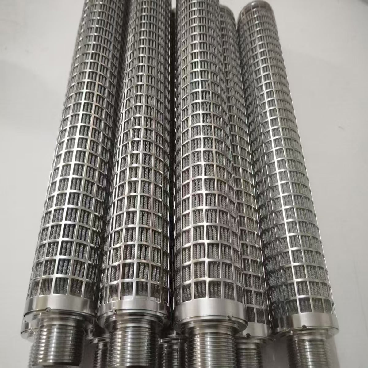
Real Maidong cylindrical filter elements with external threaded ends and support cages.
What the End Connection Must Do
Locate the element
Control radial and axial position inside the housing.
Carry assembly load
Transmit tightening, pressure, handling and removal forces.
Create the seal
Define the face, O-ring, gasket, cone or thread-seal interface.
Prevent bypass
Close unintended paths around the media and end attachment.
Metal Filter Element End Connection Comparison
Connection names are only categories. The controlled drawing must show the exact mating geometry, the surface that seals and the dimensions that remain critical after welding or assembly.
Connection type
Drawing details
Seal questions
Male / female thread
Standard, size, pitch, class, length, lead-in and shoulder
Thread seal, O-ring, gasket or separate face?
Flange or collar
OD/ID, thickness, bolt pattern, seating face and flatness
Gasket location, compression and bypass path?
Open / slip-fit end
Controlling diameter, insertion depth, stop, clearance and retention
Housing O-ring, interference fit or no seal?
Closed end cap
Cap form, depth, attachment, pressure side and unsupported area
Is the media-to-cap joint a bypass boundary?
Welded interface
Joint location, weld scope, distortion limits and post-weld dimensions
What leakage or inspection requirement applies?
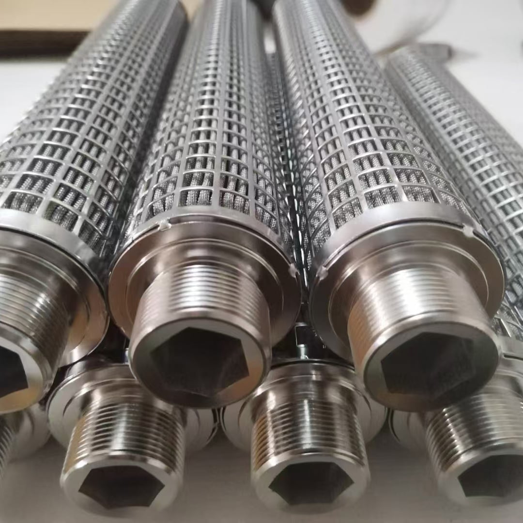
Threaded ends with internal drive features for installation; dimensions must follow the mating design.
Threaded Filter Element Connections
State the thread system and designation completely. Include male or female form, pitch, tolerance/class, engagement length, runout or relief, lead-in, shoulder position and installation feature. A photograph cannot define a thread.
Do not assume the thread is the seal. Show whether sealing occurs on the thread, an O-ring groove, a gasket face, a cone or a separate shoulder.
For a flange or collar, define OD, ID, thickness, bolt pattern if present, locating diameter, seating face and flatness. For an open slip-fit end, define insertion depth, controlling diameter, clearance, stop and retention method.
The housing drawing should show where the element seats and how it is removed without damaging the media or seal.
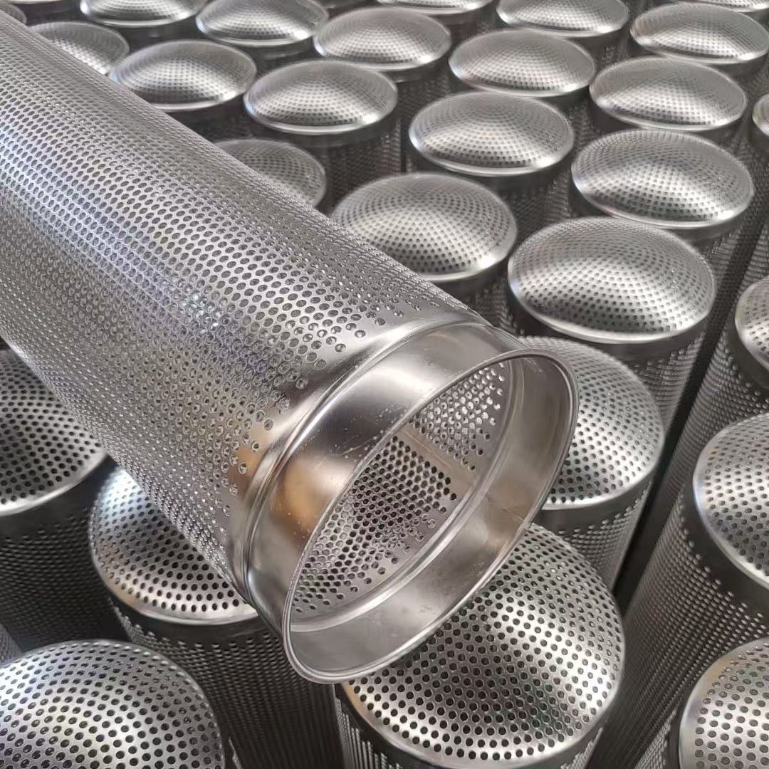
Open-rim and formed closed-end configurations shown before equipment installation.
Seal Interface and Bypass Checklist
Seal position
Mark the exact face, groove or thread region that creates the barrier.
Seal specification
State gasket/O-ring standard, material requirement and service conditions.
Compression control
Define groove, shoulder, torque or clamp travel that controls compression.
Adjacent leak paths
Review media-to-cap joints, seams, welds and housing clearances.
A micron rating describes the intended filtration medium, not leakage around the element. Seal integrity and media retention must be specified as separate requirements.
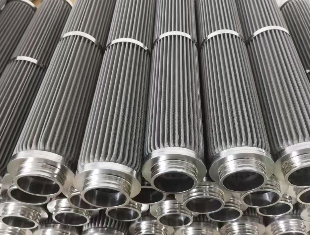
Pleated metal cartridges with drawing-specific external threaded connections.
Connection Loads and Finished Tolerances
Threading, end-cap welding and pleat assembly can affect concentricity, length, face position and sealing geometry. Put functional dimensions on the finished element drawing rather than controlling only separate parts.
State normal and reverse flow, differential pressure, installation torque or clamp load, temperature, cleaning method and removal frequency. Do not infer a pressure rating from appearance.
Real Maidong End-Connection Examples
These images show real Maidong metal filter components with several end concepts. They are visual references only; the approved drawing controls every thread, flange, seal and tolerance.
Real Maidong cylindrical filter elements with external threaded ends and support cages.
Threaded supported elements
Open-rim and formed closed-end configurations shown before equipment installation.
Open and closed ends
Pleated metal cartridges with drawing-specific external threaded connections.
Pleated threaded cartridges
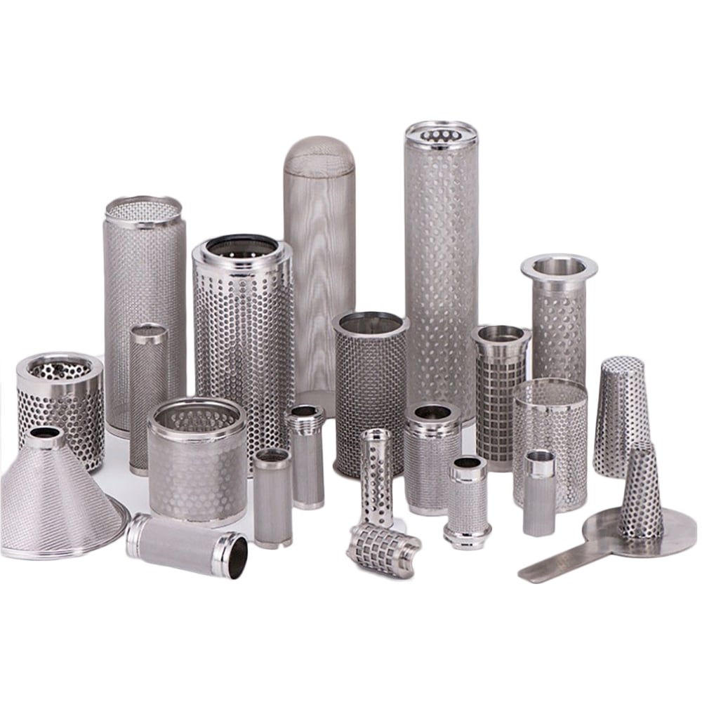
Representative cylindrical and conical metal filter forms with varied end configurations.
Custom end configurations
Match the Interface to the Filter Structure
Wire mesh cylinder
End hardware must retain the woven medium and close seam or edge bypass paths.
Pleated cartridge
End caps must locate and seal the pleated pack without obscuring the intended flow path.
Sintered element
Porous medium attachment, end machining and seal surfaces are separate drawing controls.
Perforated support body
Open area, welds and end rings must be coordinated with the fine media and housing.
There is no universal best connection. Select the interface from the housing, assembly method, pressure direction, removal access, cleaning procedure and seal requirement. The mating part and critical dimensions must be defined.
State thread standard, size, pitch, class or tolerance, male or female form, thread length, lead-in, shoulder, tightening feature, seal method, material and mating component.
Not necessarily. Some designs use a thread seal, while others use an O-ring, gasket, cone, shoulder or separate face. Mark the actual sealing surface and leakage path on the drawing.
Bypass can occur through an incorrect seal position, damaged sealing surface, unsuitable compression, dimensional mismatch, an unsealed joint or a leak path around the media-to-end-cap attachment.
Maidong can review drawing-based threaded, open, capped, collared and flange-style metal filter element enquiries. Feasibility, material, tolerances and inspection scope must be confirmed from the actual drawing.
Request an End-Connection Drawing Review
Send the filter construction, mating component, connection and seal geometry, service conditions, critical tolerances, inspection requirements and quantity.