A temporary cone strainer is a removable pipeline screen used to intercept construction debris, scale and other solids during commissioning, flushing or startup. Specify the flange fit, cone geometry, screen opening, support, flow direction and service conditions together—not as isolated dimensions.
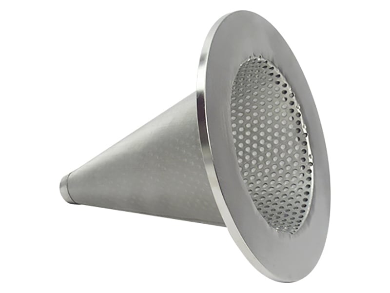
Real Maidong cone screen showing a wide rim and woven filtration body.
What a Temporary Cone Strainer Does
The strainer is installed for a defined temporary duty to protect downstream equipment while a pipeline is being cleaned or commissioned. It must fit the actual mating interface and provide a controlled path for flow and captured debris. This page covers application-specific temporary strainers; for other drawing-based cone components, see our custom conical wire mesh filter.
Startup debris capture
Intercepts weld debris, scale and loose solids identified in the commissioning plan.
Removable protection
Designed for planned inspection and removal after the defined temporary service.
Drawing-based fit
Rim, cone envelope and gasket interface must match the actual piping arrangement.
Known flow direction
Cone orientation and support are selected from the marked direction of flow and pressure loading.
Temporary Cone Strainer Specification Table
A pipe size alone is not enough to manufacture the part. Include the flange and gasket interface, finished cone envelope and operating duty on the drawing.
RFQ field
What to provide
Design relevance
Pipe / flange interface
Nominal pipe information, flange standard and class, gasket ID/OD, facing and available gap
Controls fit and sealing compatibility
Rim dimensions
OD, ID, thickness, tab or handle detail and tolerances
Defines retention between the mating faces
Cone geometry
Large-end diameter, tip diameter or closure, axial length and maximum envelope
Confirms installation clearance and screen area
Screen medium
Perforation or mesh count plus wire diameter / clear opening
Defines the retained particle opening
Support construction
Perforated backing, layer order, seam and high-pressure side
Controls structural response and bypass risk
Service data
Fluid, temperature, flow, clean and allowable differential pressure, debris type and loading
Supports a service-specific construction review
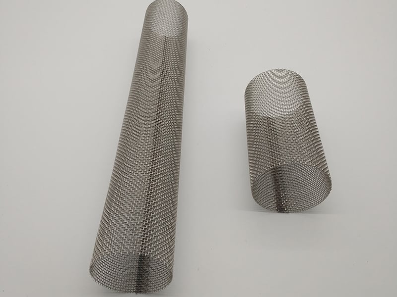
Woven mesh cone forms illustrating drawing-specific proportions.
Choose the Screen Opening from the Debris
Start with the smallest debris that must be stopped and the acceptable pressure-drop limit. For square woven mesh, give mesh count together with wire diameter or specify the clear opening. The mesh-to-micron calculator is useful for preliminary aperture comparison, but it does not establish a guaranteed filtration rating.
Where fine woven mesh needs reinforcement, define its position relative to the perforated support and the higher-pressure side.
Flow Direction and Cone Orientation
There is no safe universal instruction that every cone must point upstream or downstream. Orientation depends on the approved piping arrangement, debris-collection method, support direction and available space. Put the flow arrow and cone direction on the RFQ drawing.
Check
What to confirm
Cone direction
Show upstream/downstream and the intended direction of the cone tip on the installation drawing.
Debris collection side
State whether solids collect inside or outside the cone so the layer sequence and cleaning access are clear.
Available envelope
Verify axial clearance, nearby fittings and the space needed for installation and removal.
Pressure loading
Provide clean and allowable differential pressure; do not size the screen from line pressure alone.
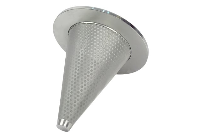
Supported conical construction with a perforated layer and wide flange.
Construction Options
Perforated cone
Uses the perforation itself as the screening opening where that opening meets the duty.
Woven mesh cone
Uses a defined wire mesh construction as the primary retention layer.
Mesh with support
Combines fine mesh with perforated backing when structural reinforcement is required.
Rim and handling tab
Uses drawing-defined flat rim, reinforced edge or removal tab compatible with the flange joint.
Real Maidong cone screen showing a wide rim and woven filtration body.
Supported conical construction with a perforated layer and wide flange.
Typical Applications
Application
Procurement intent
Pipeline commissioning
Temporary protection while construction residue and loose debris are removed.
System flushing
Defined screen stage used as part of an approved cleaning procedure.
Equipment startup
Short-duration protection for compatible pumps, valves, meters or downstream equipment.
Maintenance restart
Temporary debris interception after piping or equipment work where specified by the operator.
Woven mesh cone forms illustrating drawing-specific proportions.
Woven cone screens
Supported conical construction with a perforated layer and wide flange.
Perforated supported cone
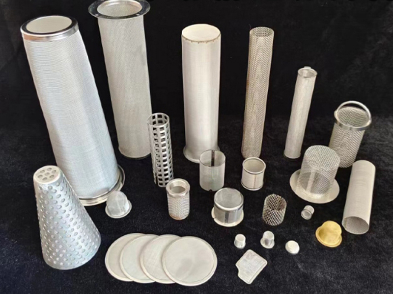
Real Maidong fabricated filter forms showing available construction approaches.
Fabricated mesh components
These photographs show real Maidong fabricated filter forms. They demonstrate construction approaches only; the supplied temporary strainer must follow the reviewed drawing and agreed specification.
Inspection, Monitoring and Removal Planning
Before installation
Verify dimensions, screen condition, layer orientation and drawing identification.
During temporary service
Monitor the system using the operator’s approved differential-pressure and inspection procedure.
At inspection
Check captured debris, screen deformation, seam condition and signs of bypass.
After the defined duty
Remove, clean or disposition the strainer according to the site plan; do not assume permanent suitability.
How to Prepare a Temporary Strainer RFQ
1. Send the piping drawing
Include flange, gasket and available envelope details.
2. Mark the flow arrow
Show cone-tip direction and debris-collection side.
3. Define the opening
State perforation or mesh count plus wire diameter.
4. Confirm support and seam
Identify layer order, joining and rim construction.
5. Add service conditions
Provide fluid, temperature, differential pressure, debris and quantity.
A temporary cone strainer is a removable screen installed in a pipeline, commonly between compatible flanges, to capture construction debris and other solids during commissioning, flushing or startup. Its dimensions and strength must match the actual piping and service conditions.
The required cone orientation depends on the installation drawing, flow direction, available space and whether debris is intended to collect inside or outside the cone. Mark the flow arrow and intended cone direction on the RFQ rather than relying on a general rule.
State the required clear opening, perforation or woven mesh count together with wire diameter. If a micron value is used, define whether it is a screen opening or a filtration rating and provide the applicable test basis.
Not always. Support is reviewed from screen fineness, open area, differential pressure, cone size, flow direction and expected debris load. Fine woven mesh often needs a stronger backing layer for demanding service.
Do not assume so. Temporary strainers are normally selected for a defined commissioning or cleanup duty. Continued service requires an engineering review of pressure drop, debris capacity, strength, inspection access and system requirements.