Stainless steel extruder screen packs combine one or more woven wire mesh layers to filter polymer melt before the die. A useful RFQ defines every layer, the pack diameter or profile, edge construction, flow direction and the screen-changer interface.
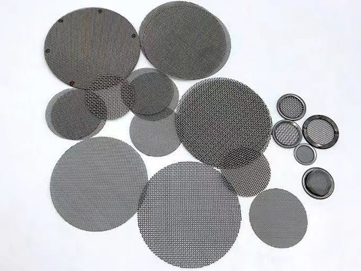
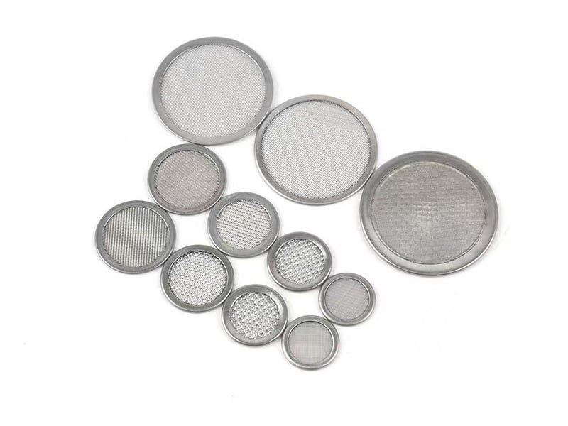
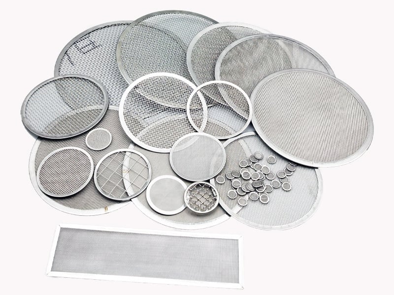
Plain-cut and edged mesh discs in different diameters and mesh constructions.
What an Extruder Screen Pack Must Control
Particle retention
The fine layer is selected around the contamination and process requirement, not mesh count alone.
Layer stability
Coarse layers or perforated supports can stabilize fine mesh under melt-flow loading.
Equipment fit
Diameter, profile, thickness and edge must match the breaker plate or screen changer.
Repeatable installation
Bonded, spot-welded or rimmed packs help preserve a defined layer sequence during handling.
Extruder Screen Pack Specification Checklist
A request such as “80 mesh, 100 mm” is incomplete. Pair mesh count with wire diameter or aperture and list the complete layer stack from the melt-entry side to the exit side.
RFQ field
Information to provide
Why it matters
Pack geometry
OD, ID if any, shape, thickness and tolerances
Controls fit and sealing in the changer
Each mesh layer
Mesh count plus wire diameter or aperture, weave and material
Defines opening, open area and strength
Layer sequence
Upstream-to-downstream order and flow direction
Prevents ambiguity in multilayer assembly
Edge construction
Plain cut, spot welded, bonded or rimmed
Affects handling, pack integrity and usable area
Process context
Polymer, temperature, pressure condition, changer type and objective
Supports an appropriate construction review
Screen Changer Interface and Layer Schedule
Write the screen pack as an ordered schedule rather than an unordered list of mesh counts. The same three layers assembled in reverse order can behave differently under the installed melt-flow direction. The screen changer drawing must control the pack profile, seat, usable area and allowable thickness.
Schedule field
Example notation
Required clarification
Flow direction
Melt entry → exit
Mark the physical upstream side on the drawing
Layer 1
Coarse protective mesh
Mesh count, wire diameter, weave and material
Layer 2
Fine filtration mesh
Opening or rating basis plus full mesh construction
Layer 3
Downstream support
Support type, orientation and attachment
Pack edge
Plain, spot welded, bonded or rimmed
Finished thickness, usable area and permitted projections
Changer fit
OD/profile, seat and clearance
Datums, tolerance, orientation feature and sealing/contact face
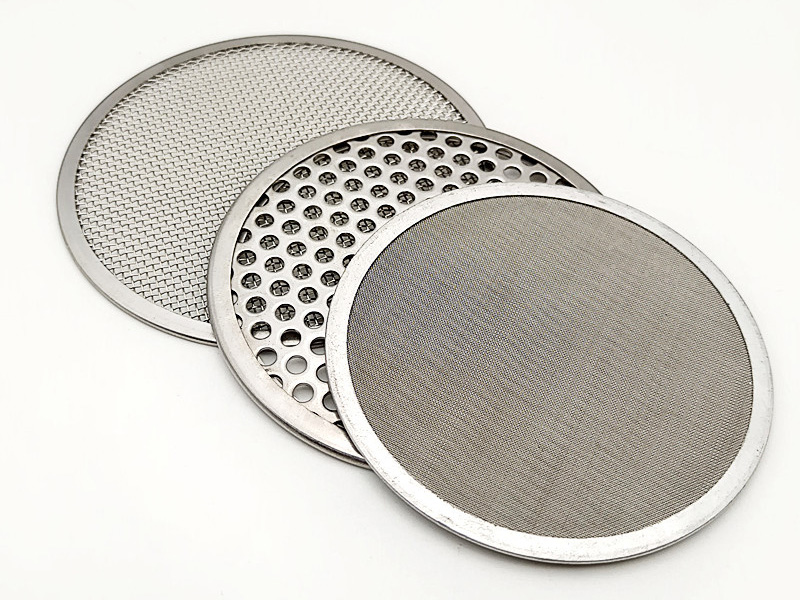
Fine filtration mesh, coarse support mesh and perforated support configurations.
Defined media and support layers
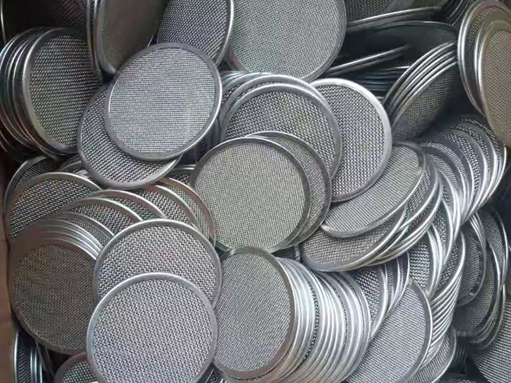
Production examples of round rimmed wire mesh screen packs.
Finished rimmed screen packs
Fine filtration mesh, coarse support mesh and perforated support configurations.
Single-Layer and Multilayer Constructions
A single woven disc is suitable when one mesh construction provides the required retention and mechanical behavior. A multilayer pack can combine a coarse protective layer, one or more filtration layers and a downstream support layer.
The exact sequence is application-specific. Show flow direction and identify every layer on the drawing or purchase specification.
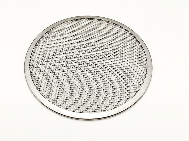
Rimmed woven mesh disc for controlled handling and installation.
Do not select by mesh count alone
For square woven mesh, clear aperture depends on both mesh count and wire diameter. The mesh-to-micron chart and calculator is a useful starting reference when these values are known.
Stainless steel wire mesh offers square-opening constructions, while Dutch weave wire mesh uses a different pore structure and should not be assigned a rating by a simple square-mesh formula.
These Maidong product images show representative mesh discs, rimmed packs and support combinations. They are construction examples, not claims that one arrangement fits every polymer process.
Production examples of round rimmed wire mesh screen packs.
Round rimmed screen pack production
Custom diameters and mesh grades prepared as rimmed screen elements.
Custom diameters and mesh grades
Round, rectangular and reinforced screen configurations for drawing-based supply.
Drawing-Based Configuration Options
Round, oval, rectangular or profile-cut shapes
Single-layer or defined multilayer stacks
Plain-cut, spot-welded, bonded or rimmed edges
Coarse woven or perforated support layers
Central holes, locating features or orientation marks
State polymer, contamination concern, changer type and operating conditions.
2. Fix the geometry
Provide diameter or profile, thickness, tolerances and interface drawing.
3. List every layer
Specify mesh count with wire diameter or aperture, weave and material.
4. Confirm the sequence
Mark flow direction, support layers and upstream-to-downstream order.
5. Complete the RFQ
Add edge construction, quantity, packaging and required documentation.
Spin Pack Filter Screens for Fiber Spinning
Maidong screen formats illustrating drawing-based shapes and layered constructions.
A spin pack is a fiber-extrusion interface, not a new filtration rating
In synthetic-fiber processing, a spin-pack filter screen is a drawing-defined mesh component or layer stack installed before the spinneret. The purchase specification must define the cavity profile, complete layer order, flow direction, edge construction and polymer duty.
The term spin pack describes the installed process assembly. It does not by itself define mesh opening, micron retention, pressure capability or compatibility. Maidong supplies the wire-mesh screen component to the customer drawing and specification.
Cavity fit
Diameter or profile, total thickness, center opening, orientation and tolerance.
Layer identity
Mesh count plus wire diameter or aperture, weave, alloy and quantity of each layer.
Flow order
Mark polymer entry and exit sides and list the stack in that physical order.
Finished edge
Define plain-cut, attached, bonded or rimmed construction and usable area.
Spin-pack RFQ field
Information to provide
Purpose
Installed profile
Diameter or outline, thickness, center opening, orientation features and tolerances
Matches the customer-defined spin-pack cavity
Layer schedule
Every mesh layer, wire diameter/aperture, weave and upstream-to-downstream order
Separates retention, distribution and support functions
Edge construction
Plain, spot attached, bonded or rimmed; allowable projection and usable area
Controls handling and installed fit
Polymer duty
Polymer or spinning process, temperature, pressure condition and contamination objective
Provides application context without inventing a universal rating
An extruder screen pack is one or more wire mesh layers installed in the melt flow path to retain contamination and support stable polymer processing. The required layer sequence depends on the material, screen changer and filtration objective.
Provide the screen changer or cavity dimensions, outside diameter or shape, layer sequence, mesh count and wire diameter or aperture for each layer, weave, material, edge construction, quantity and polymer process conditions.
No. Mesh count must be paired with wire diameter and weave. The same mesh count can have different clear openings, open area and flow behavior when wire diameter or weave changes.
A coarse woven mesh or perforated support layer can help protect and stabilize a finer filtration layer. Its placement and orientation should be defined in the approved layer sequence.
Yes. Round discs are common, but oval, rectangular, kidney-shaped and drawing-specific profiles can be reviewed. Critical dimensions, tolerances and orientation features should be shown.
Only as an approximate reference for square woven mesh when wire diameter is known. Dutch weave and multilayer screen packs require construction-specific data rather than a simple mesh-to-micron conversion.
Request a Custom Extruder Screen Pack Quotation
Send the pack dimensions, complete mesh-layer sequence, material, edge construction, flow direction, screen-changer details, polymer process conditions and quantity for review.