
Layer order, support and specification guidance for plastic extrusion.
Specify each layer by mesh count, wire diameter, weave and material, then identify the melt-flow direction and equipment support. A mesh sequence such as 20/40/80/40/20 is useful shorthand, but it is not a complete drawing, installation instruction or verified micron rating.
This guide explains how to turn a reference combination into a clear enquiry. For available shapes and constructions, view the Maidong extruder screen and screen pack product range.
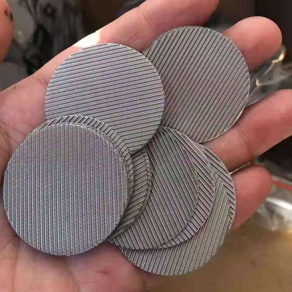
In 20/40/80/40/20, each number identifies one mesh layer. Repeated counts still represent separate layers. The notation tells a supplier the nominal sequence but leaves other critical details open.
A photograph can help identify shape and construction. It cannot verify an alloy, wire diameter or full layer schedule by itself.
| Reference sequence | What is shown | What still needs checking |
|---|---|---|
| 20 / 40 / 80 / 40 / 20 | Five layers; symmetrical mesh-count sequence | Each layer construction, approved direction and equipment support |
| 20 / 60 / 100 | Three layers; asymmetrical mesh-count sequence | Which end is upstream; the downstream support and complete drawing |
| 40 / 80 / 200 / 80 / 40 | Five layers; 200-mesh center | Wire diameter, weave, opening and support of the center layer |
Reference / custom available: these examples are starting points for discussion, not fixed standards, stock promises or recommended recipes for a specific polymer. Final construction is reviewed for the extrusion process, material, filtration requirement and equipment.
A symmetrical list can simplify identification, but the full component may still have different wire sizes, rims or orientation features on each side.
Write “Layer 1 = melt inlet” or define your own reference explicitly. Do not assume all suppliers read a list from the same end.
In a common arrangement, downstream coarse mesh supports and spaces finer screens from the breaker plate. The actual arrangement follows the equipment drawing.
Confirm cavity depth, pack and rim thickness, active area and orientation features. Backflush service requires a separate review.
Conceptual relationship: melt inlet → specified screen layers → supporting breaker plate → melt outlet. This is a process relationship, not a numbered assembly drawing for a particular machine.
If a buyer sends “20/60/100,” ask for the referenced side before quoting or manufacturing. Reversing the written list may describe the same physical pack, or an entirely different arrangement.
For regular square woven mesh, nominal geometric opening is:
Opening (mm) = 25.4 ÷ mesh count − wire diameter (mm)
Calculated illustration only: 100 mesh with 0.10 mm wire gives 0.154 mm (154 μm); 100 mesh with 0.12 mm wire gives 0.134 mm (134 μm). These examples are not product specifications or measured filtration performance.
The relationship applies to the stated square-mesh geometry. Do not apply it as a direct rating conversion for Dutch weave or a complete multilayer pack. Define whether the requirement concerns geometric opening, nominal retention or a tested rating.
For conversion background, see the mesh-to-micron reference tool; the tool does not replace the complete cloth specification.
Choose layer count after defining the filtration objective and mechanical arrangement. More layers do not automatically mean better filtration or a longer run.
Identify the contamination to retain and the required finished-product condition. Review deformable gels separately from rigid particles.
Record polymer, additives, virgin/recycled feed, throughput and melt temperature. Compare trials under similar conditions.
Check the support required by the fine mesh, overall thickness, recess depth and usable filtration area.
Agree what will be checked: product condition, pressure trend, output and physical screen condition. Follow equipment limits; do not use a generic pressure threshold.
For recycling-specific purchasing requirements, see plastic recycling extruder screen packs.
Spot welding can hold the selected layers together during handling. It does not specify the hidden layers or bond the complete filtering surface like a sintered laminate.
A rim retains edges and changes the available opening and thickness. Specify the rim material and profile independently from the mesh. Neither spot welding nor a rim alone guarantees that the pack will seal correctly in a particular cavity.
Ask the supplier to identify the layer schedule and drawing revision with each configuration, particularly when different packs look similar.
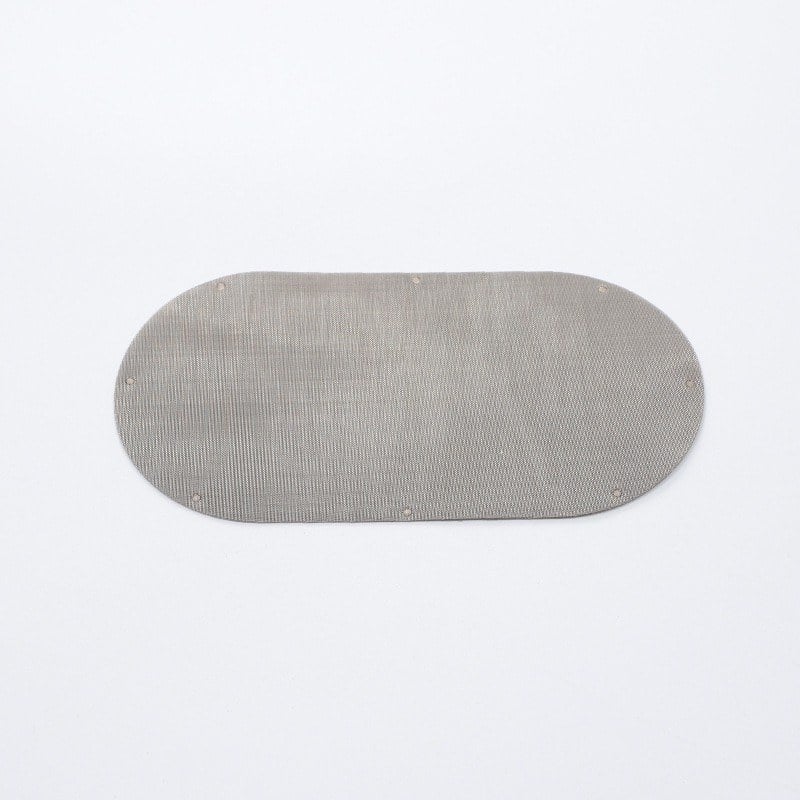
The table below uses the five positions of 20/40/80/40/20 for illustration. It deliberately leaves unconfirmed manufacturing data blank. Use the equipment-approved direction before numbering the rows.
| Layer position | Reference mesh | Information to enter |
|---|---|---|
| 1 — stated reference side | 20 | Material; wire diameter; weave; purpose; orientation |
| 2 | 40 | Material; wire diameter; weave; purpose |
| 3 | 80 | Material; wire diameter; weave; required opening/rating |
| 4 | 40 | Material; wire diameter; weave; support requirement |
| 5 — opposite side | 20 | Material; wire diameter; weave; equipment interface |
Pack-level fields: drawing number/revision; direction of numbering; outside/inside diameter or shaped profile; tolerance; total and rim thickness; edge method; weld locations; active opening; screen changer and breaker plate; quantity; destination.
Process-level fields: polymer/feed; additives and contamination; filtration objective; throughput; temperature; permitted pressure differential; backflush operation; acceptance requirements.
If a field is unknown, mark it “to confirm” rather than substituting a generic value. A clear incomplete enquiry is safer to review than an apparently complete but guessed specification.
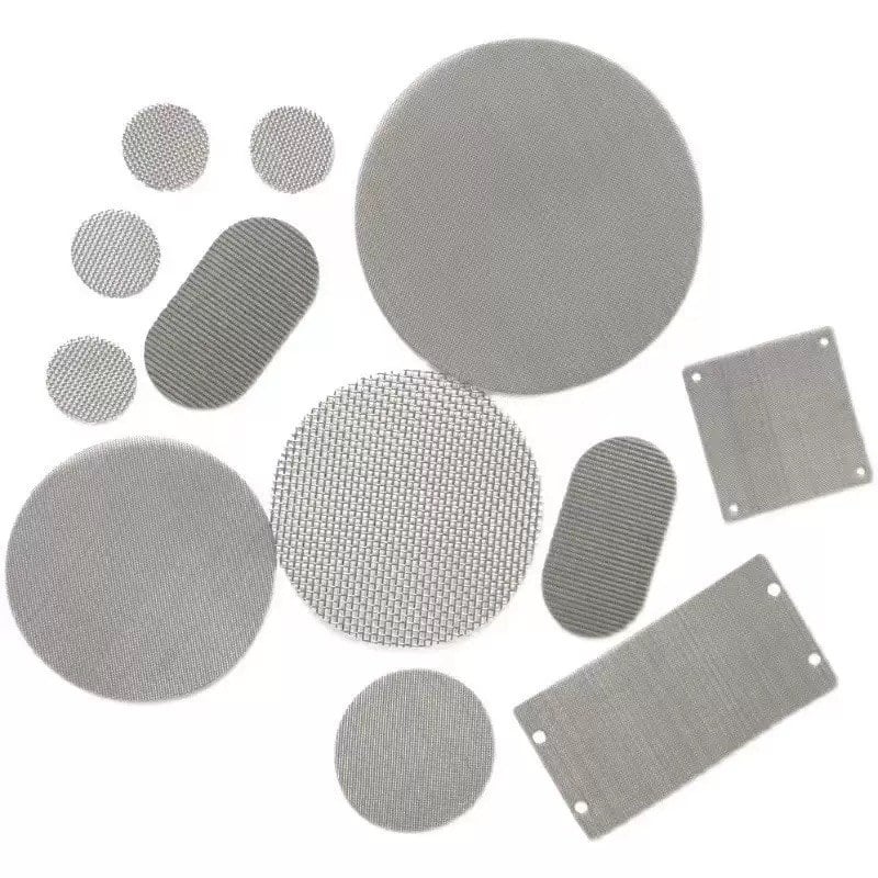
The product photos show profile examples, not a verified layer recipe. For round, oval, kidney, rectangular, annular and custom options, return to the extruder screen product page.
It identifies five separate mesh layers, with 80 mesh in the center and 40- and 20-mesh layers on either side. It does not specify wire diameter, weave, material, overall thickness or a tested filtration rating.
No. It lists three mesh counts but leaves the direction and mechanical support unclear. Provide the equipment drawing, the direction in which the sequence is written and the wire and weave details for every layer.
Use the approved equipment and layer drawing. In a common arrangement, a coarse support layer is placed toward the downstream breaker plate to support and space the finer mesh. A sequence without a stated direction is not an installation instruction.
Symmetry of mesh numbers alone is insufficient. Different wire sizes, weaves, material grades, rims or orientation features may make the two sides different. Confirm whether the complete component is reversible.
No. Wire diameter and weave determine the mesh geometry, and the assembled pack needs an appropriate rating definition. A geometric opening is not a guarantee that every particle above that size will be removed.
No. Extra layers change support, spacing, thickness and flow resistance. Select the complete construction for the equipment and filtration objective rather than choosing by layer count alone.
Do not assume the same specification will perform identically. Review contamination, polymer and additives, throughput, melt conditions, screen area and the required product quality.
Send the same drawing revision, layer schedule, material, wire diameter, weave, dimensions, edge details and quantity to each supplier. Identify the inlet and breaker-plate sides and any features that must not be substituted.
Send Maidong your current pack specification, dimensioned drawing or measured photographs. Include the quantity and extrusion process so we can review the requested construction and prepare a quotation.
The distinction between mesh count and wire diameter, and the support/spacing role of layers, is discussed in the SPE Extrusion Division’s Screen Pack Selection and Assembling a Screen Pack. These historical technical notes provide background; equipment-specific requirements take precedence.