Filter Cylinder Roundness and End Squareness Guide
A filter cylinder can meet a diameter reading and still have a shape or end-alignment problem. Specify the characteristic, the reference and the inspection condition before comparing results.
This guide helps buyers distinguish a practical fit check from a defined geometric inspection.

Keep Three Questions Separate
Size
Which OD or ID controls fit, at which location, and under what measurement condition?
Roundness
How is the cross-sectional form evaluated, with what sampling and agreed method?
End orientation
Which end surface must be perpendicular to which drawing-defined reference?
A fit trial can show whether a particular part enters a particular seat. It does not replace all dimensional or geometric requirements. Likewise, one circular section does not establish the shape of the entire cylinder along its length.
Define the Surface Being Evaluated
A wire mesh surface contains wires, openings and possibly a raised seam. A rigid end ring, a perforated support and the mesh envelope are different features. Identify which feature is responsible for locating the part in the equipment and which feature the inspection result describes.
Mark axial sections and angular locations on a sketch. Identify seams and local fittings rather than quietly excluding inconvenient readings. The sampling strategy and treatment of local features must suit the specified characteristic; do not invent a universal number of points.
Diameter variation is useful—but label it correctly
Several two-point diameter readings can help screen for size variation. They cannot be assumed to capture every form error. Retain readings with their positions and method. If formal roundness is required, agree an appropriate evaluation and report its conditions.
See Mitutoyo’s overview of roundness evaluation methods for general metrology context. Application to an open mesh surface requires a suitable agreed method.
Identify the End Face and Reference Axis
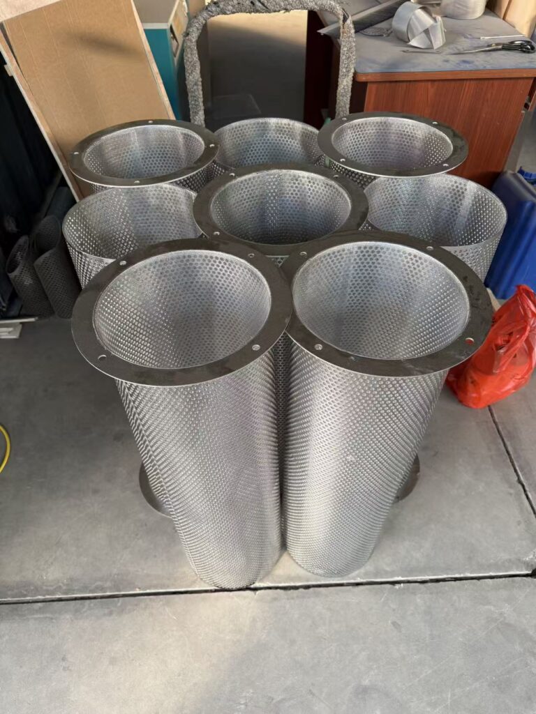
For a flanged filter, the functional contact face may differ from the cut mesh edge. Identify the actual surface to assess and the datum feature used to establish the reference axis. A loosely supported or distorted mesh wall may not establish a repeatable equipment axis.
A square placed against a convenient side or an indicator used during rotation can be a useful agreed shop check. Neither should automatically be reported as formal perpendicularity. Alignment, face form and setup can affect the reading.
Where geometric tolerancing applies, use the specified drawing convention and a measurement strategy consistent with it. The ZEISS measuring strategies reference includes perpendicularity-to-axis evaluation; this does not imply Maidong owns the illustrated equipment.
Agree Support Conditions Before Comparing Parts
A mandrel, clamp or fixture can change a flexible cylinder. Record whether the test evaluates the part in its free condition or under a defined installation-like restraint. Use comparable conditions for supplier and incoming inspection. Do not force a part into shape and report the result as its original geometry.
| Feature and requirement | OD/ID, cross-sectional form or a named end face; keep these distinct. |
|---|---|
| Reference | Drawing-defined datum feature or explicitly agreed shop reference. |
| Part condition | Free, supported or restrained; fixture contact points and any applied load. |
| Measurement locations | Marked sections, angular positions and treatment of seams or attachments. |
| Method and instrument | Contact arrangement, sampling/evaluation and relevant instrument capability. |
| Acceptance | Drawing revision, agreed limit and decision rule; unresolved items remain open. |
| Report | Actual readings/result, setup description, part ID and exceptions. |
The drawing checklist organizes the wider specification. If only an old part exists, start with the sample measurement guide before assigning new acceptance limits.
Example RFQ Inspection Note
For part [number/revision], assess [named feature] against [defined reference] in [free/supported/restrained] condition. The drawing marks measurement locations and any seam treatment.
Required method and evaluation: [agreed details]. Acceptance: [drawing requirement and decision rule]. Record the setup and results separately for size, form and end orientation. Please identify any measurement limitations before quotation.
This template contains no default tolerance. Fill the brackets for the actual component. Rework or a fixture change should not silently change the acceptance condition.
Roundness and End Squareness FAQ
No. Diameter readings describe size at selected locations. They do not automatically establish the complete cross-sectional form or compliance with a roundness requirement.
Report that result as the diameter variation obtained by the stated method. Do not relabel it as a formal roundness result unless the agreed specification explicitly defines that evaluation.
Identify the drawing-defined reference, such as an axis established from a specified rigid cylindrical feature. Do not assume that any convenient mesh surface establishes the intended axis.
The agreed inspection condition should specify whether it is free, supported or restrained. Clamping can change the shape. A restrained result must not be presented as a free-state result.
Not automatically. The setup and datum establishment can introduce other effects. Report the actual method and characteristic rather than renaming a shop-floor check as a different geometric tolerance.
There is no single acceptance value offered by this guide. Agree limits, references and methods for the actual fit, construction and drawing before quotation or inspection.
Match the Inspection to the Equipment Fit
Send the controlled drawing, mating-interface information and required inspection conditions with your filter enquiry.