Custom stainless steel welded wire mesh panels are finished flat or formed components made to a controlled size and grid. The purchasing specification should define the opening, wire diameters, cut pattern, edge finish, frame, bends and mounting interface—not only the base mesh.
A flat panel drawing should control finished size, grid direction, edge condition and support-wire positions.
What Makes a Welded Mesh Panel Drawing-Ready?
Finished envelope
Length, width, flatness and corner geometry measured from stated datums.
Grid definition
Opening, line-wire and cross-wire diameters, direction and support-wire layout.
Edge condition
Flush-cut ends, retained projections, border wire or separate perimeter frame.
Installed interface
Bends, tabs, holes, clips and equipment-contact surfaces located on the drawing.
Welded Wire Mesh Panel RFQ Table
Specification field
What to define
Purchasing reason
Finished panel size
Length, width, thickness envelope, squareness and flatness
Controls assembly fit and usable area
Grid and wire
Opening in both directions, wire diameters and grid orientation
Defines retention, clearance and structural layout
Cut pattern
Flush cut, projecting wire length, symmetry and edge datum
Avoids sharp-end and fit assumptions
Edge reinforcement
Border wire, perimeter frame, corner joint and attachment method
Changes envelope and edge rigidity
Formed features
Bend line, angle, radius, tabs, holes and offsets
Defines the installed interface
Service inputs
Support span, load, temperature, medium and cleaning method
Supports construction and material review
Cut size and retained or flush wire ends should be stated explicitly.
Cut-to-Size Flat Panels
Flat panels suit guards, separators, support surfaces and equipment inserts when the finished outline is controlled. State whether the perimeter must be flush, retain a specific wire projection or follow a symmetric grid pattern.
A perimeter frame can protect the edge and provide a more defined assembly interface. The drawing should specify frame wire or profile, corner radii, joint locations, overall envelope and where the welded grid meets the frame.
A perimeter frame changes the finished envelope, corner geometry and mounting interface.
Edge and Frame Configurations
Flush-cut edge
Wire ends trimmed near the outer line; acceptable projection must still be stated.
Retained wire ends
Defined projections used where the design needs hooks, clearance or a later attachment.
Border-wire edge
A heavier edge wire integrated with the grid to control the perimeter.
Separate frame
Round wire or another drawing-defined member attached around the finished panel.
Cut size and retained or flush wire ends should be stated explicitly.
A perimeter frame changes the finished envelope, corner geometry and mounting interface.
Bends, tabs and contact points need drawing datums, angles and clearances.
Formed Panels, Bends and Mounting Tabs
Forming turns a flat grid into an equipment-specific component. Give bend sequence, angle, inside radius, tab length, hole position and the faces that control installation. Also identify any area that must remain flat or free of wire projections.
State the required stainless steel grade when chemistry or service compatibility matters.
Opening vs part size
Compare both opening directions with the smallest retained part and its possible orientation.
Wire and support span
Give load distribution, support points and allowable deflection; do not infer a rating from a photo.
For material-selection context, compare 304 and 316 stainless steel wire mesh. Final suitability depends on the actual medium, temperature, cleaning method and mechanical interface.
Custom Panel Configurations
Equipment guard insert
Flat or framed mesh installed within a customer-defined guard assembly.
Support or separator panel
Grid direction and reinforcement positioned around the supported item and span.
Formed equipment component
Bends, tabs, stops or guide features made to the installation drawing.
Rack or tray insert
Finished panel placed in a carrier, rack or processing assembly.
Screen support panel
Open welded grid used behind a finer medium where the layer interface is defined.
Custom fabricated mesh part
Nonstandard outline, cutouts or frame details supplied from drawing.
Maidong Welded Mesh Panel Examples
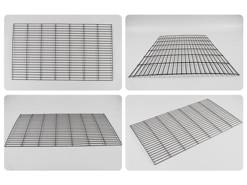
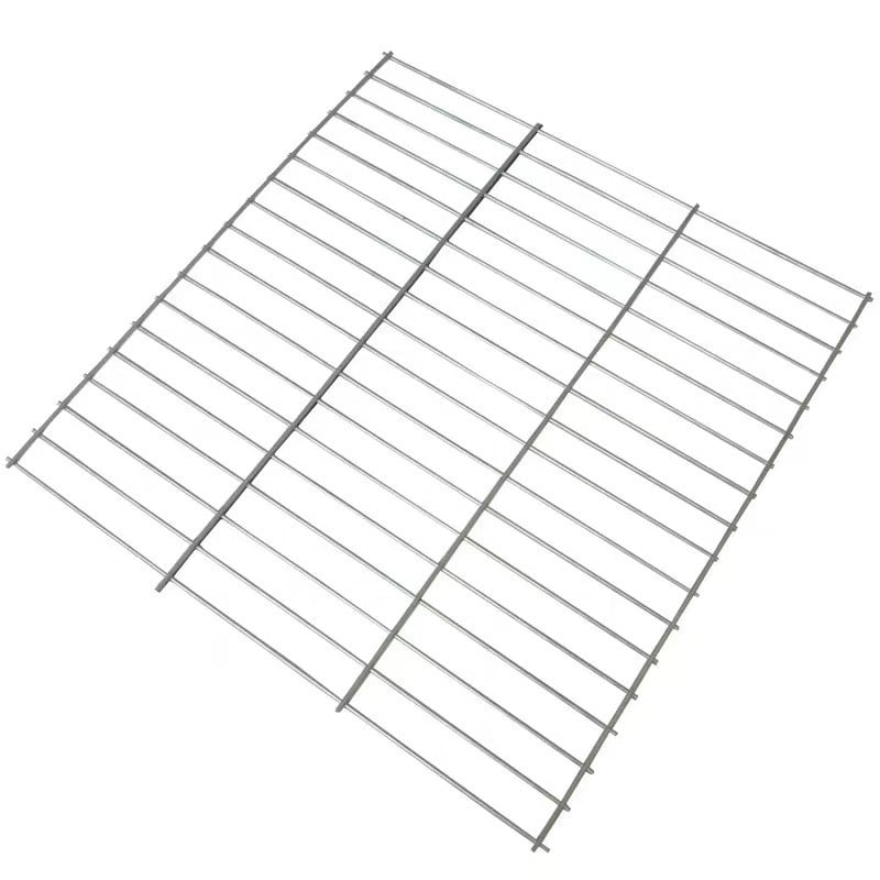
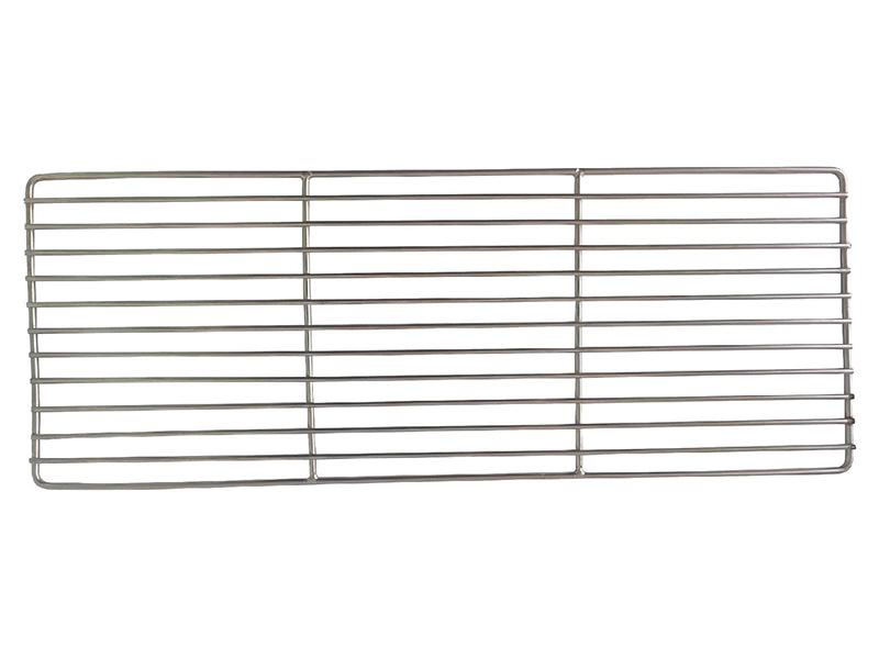
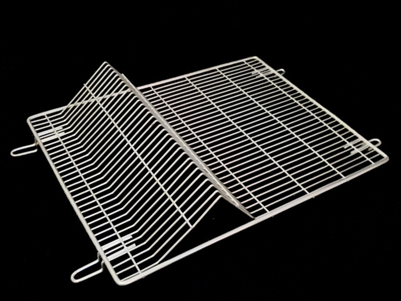
These Maidong material-library images show flat, framed and formed panel directions. They are configuration references only; the approved drawing controls final dimensions, tolerances, service suitability and inspection.
A flat panel drawing should control finished size, grid direction, edge condition and support-wire positions.
Flat cut panel views
A perimeter frame changes the finished envelope, corner geometry and mounting interface.
Rounded perimeter frame
Bends, tabs and contact points need drawing datums, angles and clearances.
Formed panel with tabs
How to Prepare a Welded Mesh Panel RFQ
1. Define the grid
Opening, wire diameters, orientation and support-wire pattern.
2. Define finished size
Envelope, squareness, flatness, corners and datums.
3. Define every edge
Flush cut, projection, border wire or perimeter frame.
4. Add interfaces
Bends, tabs, holes, clips and contact surfaces.
5. Add service data
Support, load, medium, temperature, cleaning, quantity and revision.
Provide finished length and width, wire diameters, opening and orientation, edge condition, frame or border wire, bends, tabs, holes or mounting features, material, quantity, tolerances and the intended equipment interface.
Yes. A cut panel is a finished-size component rather than roll material. The RFQ should define whether edges are flush-cut, retain projecting wires, carry a border wire or are enclosed by a frame.
A border wire is normally part of the welded grid edge. A perimeter frame is a separate heavier wire or formed member attached around the panel. They produce different envelope, rigidity and corner details.
A panel can be reviewed with drawing-defined bends, formed edges, tabs or attachment features. State bend line, angle, inside radius, tab position and the surfaces that control installed fit.
For rectangular openings, show which opening dimension runs parallel to panel length. Also locate heavier support wires and state whether the cut pattern must be symmetric or aligned to an edge datum.
Load capacity should not be inferred from wire diameter or a photograph. Provide the span, support method, load magnitude and distribution, allowable deflection and safety requirements for engineering review and application validation.
Send the Finished Panel Drawing
Include the grid, material, finished envelope, edge condition, frame, bends, tabs, installation datums, tolerances, service inputs, quantity and drawing revision.