Wire Mesh Filter Edge Types: Selection and Drawing Guide
A wire mesh filter edge controls handling, layer containment, installation fit and the path where fluid could bypass the media. Choose the edge from the housing interface and sealing method—not from the filter shape alone.
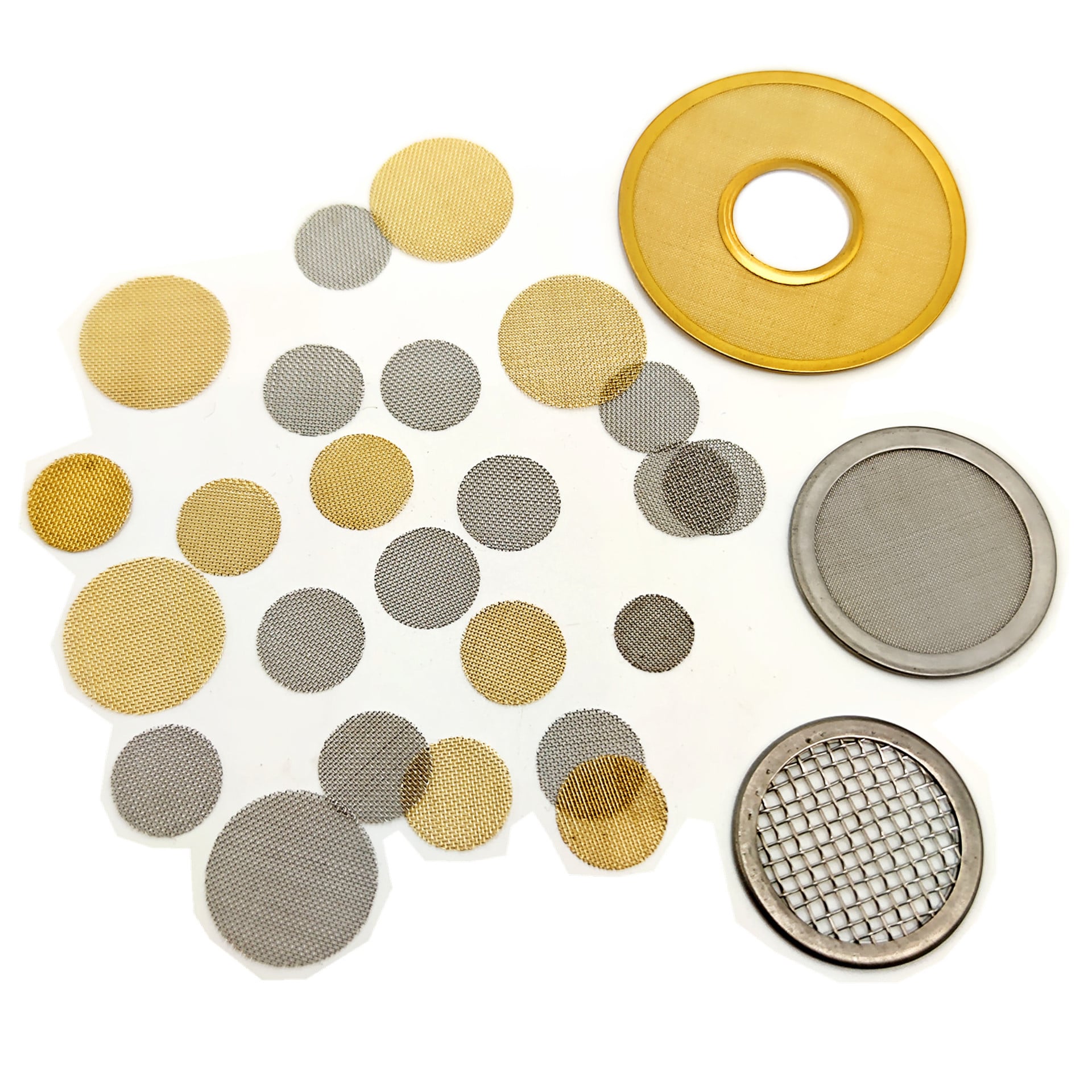
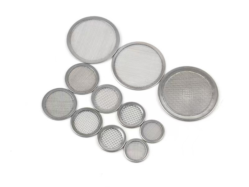
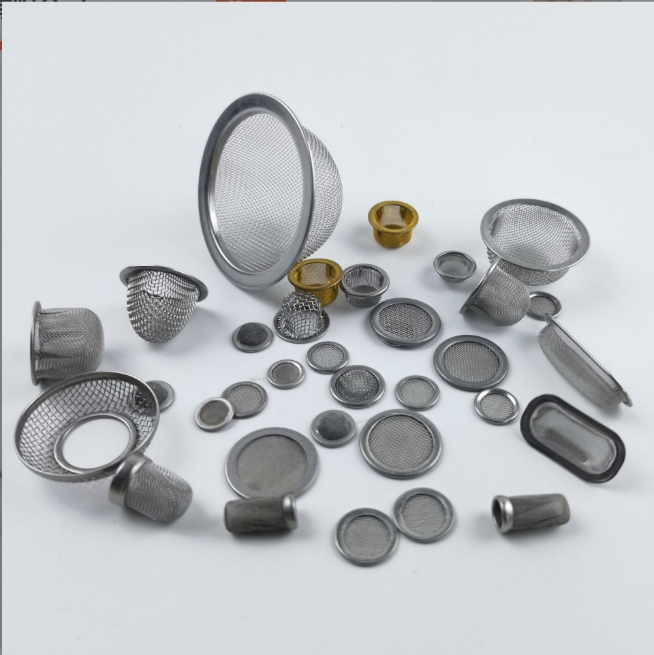
Plain-cut and rimmed screens illustrate why edge construction must be specified separately from filter media.
Direct Answer: Match the Edge to the Interface
Housing-captured mesh
Plain cut or a simple contained edge may be sufficient when the housing controls the perimeter.
Handled component
A folded, welded or rimmed edge can contain cut wires and stabilize the finished outline.
Multilayer screen
The edge must keep every layer aligned and define how the stack terminates.
Sealing surface
Rim, gasket and housing contact must form one defined anti-bypass path.
Wire Mesh Filter Edge Type Comparison
Edge type
Typical role
Drawing fields
Main risk if vague
Plain cut
Mesh captured completely by another component
Outline, tolerance, exposed-wire rule and handling
Fraying, distortion or uncovered bypass path
Folded / hemmed
Mesh perimeter turned back to contain cut wires
Fold width, direction, layers and finished thickness
Uneven thickness or reduced active area
Welded perimeter
Edge stabilized or layers joined around the outline
Weld location, width, continuity and distortion limit
Uncontrolled heat effect, gaps or dimensional change
Bonded edge
Layers or edge member joined by a specified validated process
Material/process specification, bond zone and service limits
Compatibility or integrity assumed without evidence
Metal rim / frame
Cut wires contained and a repeatable interface created
Material, profile, width, joint, OD/ID and thickness
Wrong fit, active area or seal contact
Gasket-captured
Mesh or rim compressed within a defined sealing stack
Gasket, compression, contact width, groove and surface datum
Media bypass despite correct mesh rating
Finished outside diameter, rim width and total thickness belong on the drawing.
Plain-Cut vs Metal-Rimmed Screens
Plain-cut mesh preserves more usable area and can be efficient when another part captures the perimeter. A metal rim contains wire ends, helps align layers and creates a controlled finished outline, but it also occupies area and adds thickness.
Define the clamped width, surface datum, gasket and compression path.
Located in a recess
Control finished outline, thickness, corner or diameter tolerance and removal clearance.
Inserted as a loose screen
Control handling stiffness, exposed wires and orientation features.
Joined into an assembly
Define edge member, attachment, heat or bond zone and bypass requirement.
Sealing and Bypass: Follow the Complete Path
A correct mesh opening does not prevent fluid from travelling around the mesh. Trace the path from filtration media to edge treatment, rim or frame, gasket and housing. Identify every joint and contact surface that is expected to block bypass.
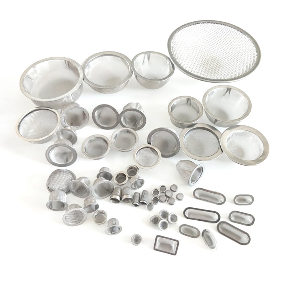
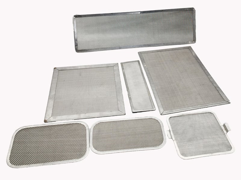
These Maidong material-library images show plain discs, metal-rimmed screens, formed components and rectangular frames. They illustrate edge directions only; the approved drawing controls the final joining, sealing and inspection requirements.
Plain-cut and rimmed screens illustrate why edge construction must be specified separately from filter media.
Plain and rimmed discs
Finished outside diameter, rim width and total thickness belong on the drawing.
Round rimmed screens
Non-round framed screens require outline, corner, frame-joint and datum controls.
Rectangular frames
Edge Detail Drawing Checklist
1. Show the section
Draw how mesh, layers, edge member and gasket meet.
2. Mark datums
Identify the locating and sealing surfaces.
3. Dimension the edge
Add width, profile, OD/ID, thickness and tolerances.
4. Define joining
State fold, weld, bond or capture requirements and joint location.
5. Define acceptance
Add exposed-wire, bypass, dimensional and inspection criteria.
A plain-cut edge is the simplest when the receiving housing fully captures the mesh and loose wires, distortion and bypass can be controlled. Finished outline, tolerance and handling requirements still need definition.
A metal rim is useful when the perimeter must contain cut wires, align layers, improve handling or create a repeatable installation surface. State rim material, profile, width, joint, total thickness and contact surfaces.
Not automatically. Bypass depends on the entire sealing path: mesh-to-rim joining, rim geometry, gasket or housing contact, compression and dimensional fit. The drawing should identify the intended seal and acceptance requirement.
A folded edge uses the mesh itself or an integral material fold to contain the perimeter. A separate rim adds another formed member around the mesh. They differ in thickness, rigidity, active area and equipment interface.
Yes, but the drawing should list every layer, order, alignment and joining method. State whether layers are only perimeter-contained, spot joined or bonded by another validated process.
Include finished outline, OD/ID or profile, edge cross-section, rim or fold width, total thickness, joint position, layer termination, sealing face, datums, tolerances, burr or exposed-wire rules and inspection criteria.
Review the Edge Before Finalizing the Mesh Screen
Send the media, layer order, finished outline, edge section, sealing path, housing interface, tolerances, service conditions, quantity and drawing revision.